25 / 96
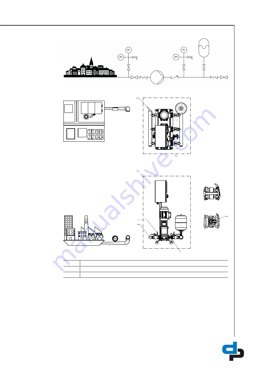
4.8.1 Inlet conditions, version M
Fig. 6:
M = Inlet side of pressure booster system connected to the municipal water supply,
suction head operation
1
C
1
2
C
3
Fig. 7:
Scope of supply for version M
1
Suction line (included in DP’s scope of supply)
2
Lift check valve (included in DP’s scope of supply)
3
Dry running protection (included in DP’s scope of supply)
Summary of Contents for Hydro-Unit Utility Line F
Page 29: ...29 96 1 2 Fig 12 PE connection 1 Earthing terminal 2 Location of power connection ...
Page 58: ...58 96 ...
Page 92: ...92 96 T Tank 79 Timers 73 W Warnings 9 Warranty claims 7 ...
Page 93: ......
Page 94: ......
Page 95: ......


