OP000529
3-8
Operation
Starting Engine With a Booster Cable
If the batteries are drained during starting procedures, jump start
engine using auxiliary or booster batteries according to the
following procedure;
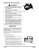
Connecting the Booster Batteries
1.
Shut down engine of the machine on which booster
batteries (3, Figure 15) are mounted.
2.
Connect one end of red cable (1, Figure 15) to the positive
(+) terminal of the machine batteries (4), and the other end
to the positive (+) terminal of the booster batteries.
3.
Connect one end of black cable (2, Figure 15) to the
negative (-) terminal of the booster batteries (3), and then
make ground connection to the upper frame (5) of the
machine to be started with the other end of black (-) cable
(2, Figure 15). When making the last connection to upper
frame, be sure to connect the cable end as far away from
HAOA440L
Figure 14
WARNING!
1.
An explosive gas is produced while batteries are in
use or being charged. Keep flames or sparks away
from the battery area.
2.
Charge batteries in a well ventilated area.
3.
Always wear eye protection when starting a machine
with jumper cables.
4.
Improper jump starting procedures can cause an
explosion resulting in personal injury.
5.
Jump start vehicles on dry ground or concrete. Do not
jump start the machine on a steel floor, because the
floor is always grounded.
6.
When starting from another machine, make sure the
machines do not touch.
7.
Always connect the auxiliary battery positive (+)
terminal too depleted battery positive (+) terminal first.
Then connect auxiliary battery negative (-) terminal to
the frame of the depleted battery machine second.
8.
Connect positive cable first when installing cables and
disconnect the negative cable first when removing.
IMPORTANT
The machine has a 24V (-) negative ground electrical
system. Use the same capacity 24V booster batteries when
jump starting engine.
1
4
5
3
2
RED
BLACK
ARO0440L
Figure 15
Summary of Contents for DX190W
Page 2: ......
Page 71: ...OP000528 2 3 Operating Controls ...
Page 128: ...OP000528 Operating Controls 2 60 CD Player Optional AST DIR FG000109 Figure 135 ...
Page 196: ......
Page 292: ...OP000530 Inspection Maintenance and Adjustment 4 96 ...
Page 304: ...OP000440 6 8 Troubleshooting ...


