


OP000528
2-1
Operating Controls
OP000528
2
Operating Controls
The "Operating Controls" section presented here consists of the
following groups:
1.
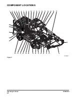
“Component Locations” on page 2-4
2.
3.
“Operational Controls and Panels” on page 2-8
4.
“Instrument Panel” on page 2-26
5.
“Multifunction Gauge and Graphic Information” on
page 2-32
6.
“Mode Selector Buttons” on page 2-38
7.
“Setting Main Menu” on page 2-40
8.
9.
“Operation Selection Display” on page 2-51
10. “Heater and Air Conditioner Control Panel” on page 2-53
12. “Miscellaneous Electrical Devices” on page 2-61
13. “Seat Adjustment” on page 2-63
14. “Ceiling Cover” on page 2-67
15. “Front Windows” on page 2-68
16. “Door Side Latch” on page 2-70
17. “Cabin Storage Compartments” on page 2-71
22. “Door Window Holder” on page 2-73
23. “Emergency Glass Breaking Tool” on page 2-73
24. “Miscellaneous Access Covers and Doors” on page 2-74
25. “Swing Lock Pin and Mechanism” on page 2-76
26. “Wheel Chocks” on page 2-76
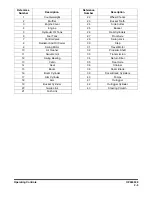
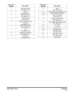
Each group is explained with a point location drawing or photo
and a brief description of each control, switch, gauge or valve.
Indicator lights work besides the gauges on the instrument
panel. The operator should monitor machine pressure on the
instrument panel along with indicator lights. These lights will only
show that there is a problem.
Summary of Contents for DX190W
Page 2: ......
Page 71: ...OP000528 2 3 Operating Controls ...
Page 128: ...OP000528 Operating Controls 2 60 CD Player Optional AST DIR FG000109 Figure 135 ...
Page 196: ......
Page 292: ...OP000530 Inspection Maintenance and Adjustment 4 96 ...
Page 304: ...OP000440 6 8 Troubleshooting ...