OP000509
Inspection, Maintenance and Adjustment
4-26
2.
Check O-ring for damages and replace if necessary.
Check position of O-ring at surface of hole.
3.
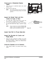
Place the cover on the access hole. Make sure the
spring retaining cup (1, Figure 22) in the lower section
of the cover is lined up with the spring. The filter
assembly rod must be in a vertical position and
perpendicular to the base of the tank. The cover can
be rotated to align the rod into a vertical position.
4.
Tighten mounting bolts to 4.84 kg•m (35 ft lb).
Check for Leaks in Hydraulic System
1.
Perform a daily walk-around inspection to make sure
that the hoses, piping, fittings, cylinders and hydraulic
motors are not showing any signs of leakage. If any is
noted, determine the source of the leak and repair.
Fill Fuel Tank
1.
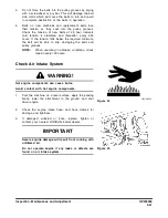
At end of each work day, fill fuel tank. Add fuel
through fuel fill cap (Figure 23). When working at a
temperature of 0°C (32°F) or higher, use ASTM No.
2-D or its equivalent. At temperatures below 0°C (32°F)
use ASTM No. 1-D or its equivalent.
2.
Securely tighten cap after fueling.
NOTE:
If breather holes in cap are clogged, a vacuum
may form in the tank preventing proper fuel flow
to engine. Keep holes in fuel cap clean.
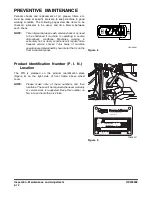
Figure 22
FG002189
1
FG001689
Figure 23
WARNING!
Use extreme safety precautions while refueling to prevent
explosions or fire.
Immediately clean up any spilt fuel.
FG001690
Figure 24
Summary of Contents for DL200
Page 2: ......
Page 6: ...K1024537E Table of Contents IV ...
Page 7: ...K1024537E I I Presentation 1Presentation PRESENTATION FG008047 Figure 1 ...
Page 17: ...OP000506 1 5 Safety 1 3 10 12 6 4 11 5 9 8 3 7 10 9 4 6 2 FG008049 Figure 1 ...
Page 60: ...OP000506 Safety 1 48 ...
Page 112: ...OP000507 Operating Controls 2 52 CD Player Optional AST DIR FG000109 Figure 101 ...
Page 122: ...OP000507 Operating Controls 2 62 ...
Page 232: ...OP000509 Inspection Maintenance and Adjustment 4 88 ...
Page 242: ...OP000040 Troubleshooting 6 8 ...
Page 252: ...OP000510 Specification 7 10 ...

