45
Donaldson Company, Inc.
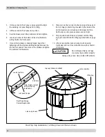
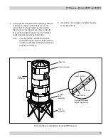
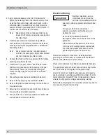
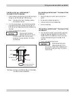
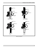
4. Apply hardware adhesive to the 3/8-in hardware and
tighten the Centering Plate to the tube sheet plate. If the
Centering Plate will not align with a bolt location on the
tube sheet plate, the assembly is out of alignment and
needs to be fixed by repeating step 3. Check rotation of
the arms and repeat this step if necessary.
Note: Repositioning of the air tank assembly may be
required for this step to ensure the cleaning arms
can rotate freely.
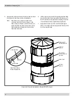
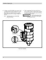
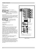
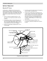
5. Install the gear reducer and sprocket along with the
chain tensioner to the H-Frame (reference the included
Cleaning Assembly drawing AD3627301 or AD3627302
depending on size).
Note: Drive sprocket, tensioner, and idler sprocket
must lie in the same plane. Adjust driver sprocket
and chain tensioner to achieve results.
6. Connect the chain from the drive sprocket to the rotating
assembly using the master link.
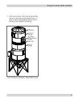
7. Install motor to the gear reducer. Check that the motor
shaft key is in place and enters the keyway in the gear
drive correctly. Fasten the motor flange to the gear
reducer housing using the four hex head cap screws
supplied.
8. Ensure the gearbox has been prefilled with lubricant.
9. Remove the top pipe plug and install the breather.
10. Remove the plastic exhaust-port plug from the bottom of
the solenoid valve.
11. Adjust the drive sprocket, tensioner sprocket and idler so
they are in the same horizontal plane.
12. Wire the motor to a customer-supplied motor starter with
overload and short circuit protection.
Electrical Wiring
Electrical installation, service,
or maintenance work must be
performed by a qualified electrician
and comply with all applicable national and local
codes.
Turn power off and lock out electrical
power sources before performing service or
maintenance work.
Do not install in classified hazardous
atmospheres without an enclosure rated for the
application.
All electrical wiring and connections, including electrical
grounding, should be made in accordance with the National
Electric Code (NFPA No. 70-latest edition).
Check local ordinances for additional requirements that apply.
The appropriate wiring schematic and electrical rating must be
used. See collector’s rating plate for required voltage.
An electric disconnect switch having adequate amp capacity
shall be installed in accordance with Part IX, Article 430 of the
National Electrical Code (NFPA No. 70-latest edition). Check
collector’s rating plate for voltage and amperage ratings.
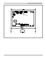
Refer to the wiring diagram for the number of wires required for
main power wiring and remote wiring.
If the collector was supplied with an electrical
control panel, the wiring diagram supplied with
the control panel takes precedence over the
general diagrams shown in this manual.


