background image

41

Donaldson Company, Inc.

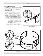
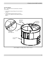
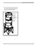
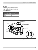
involute 

inlet 

assembly

dirty air plenum

assembly

optional explosion

vent

hopper

assembly

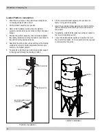
sealant pattern

upper flange

Upper Flange

Sealant Application

bolt hole

tube sheet

Dirty Air Plenum Installation, Model RFWP shown

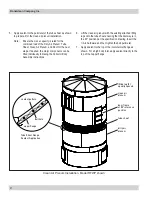
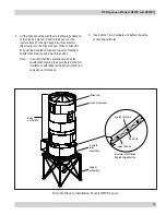
7.  Lift the dirty air plenum assembly with tube sheet onto 

the involute inlet assembly. For the high body inlet, this 

assembly lifts directly onto the hopper flange. Properly 

orient the dirty air plenum assembly to the hopper inlet 

assembly and lower into place. 


Note:   It is critical that the orientation matches the 

specification drawing to ensure there will be NO 

interference with ladder and platform locations.

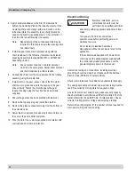
8.  Insert all hardware and then tighten the entire connecting 

perimeter.

9.  Remove the angle iron lifting lugs.
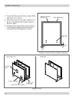
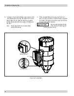
10.  Apply sealant to the perimeter of the tube sheet as shown 

to prepare it for the clean air plenum installation.

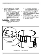
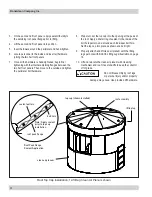
4.  Lower the tube sheet into position. Insert only the 5/8-in 

hardware required to connect the tube sheet radial 

stiffeners to the internal gussets and tighten.

Take precaution against pinching 

when handling and installing the 

tube sheet into the Dirty Air Plenum.

5.  Apply sealant to the top of the involute inlet flange as 

shown. For a high body inlet, apply sealant directly to the 

top of the hopper flange. 

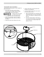
6.  Properly attach and lift dirty air plenum assembly with the 

lifting lugs per note with Bolt-On Lifting Lugs illustration.  

Summary of Contents for RFWP

Page 1: ... contains specific precautions related to worker safety The hazard alert image denotes safety related instructions and warnings in this manual DO NOT install operate or perform maintenance on this collector until you have read and understood the instructions precautions and warnings contained within this manual IOM AD3670201 ENG Revision 4 English Master Language ...

Page 2: ...njury This manual has been supplied to assist with the installation operation and maintenance for the collector purchased Please read the manual before installing operating or performing maintenance on the collector as it contains specific precautions for worker safety It is the owner s responsibility to ensure that this manual is available for use by installers operators and maintenance personnel...

Page 3: ...y 28 Cleaning System Operation 31 Cleaning Mechanism Installation 32 Roof Installation 34 Collector Body Assembly for Lower Crane Capacity 40 Ladder Platform Installation 43 Cleaning System Assembly and Adjustment 44 Electrical Wiring 45 Solid State Timer Installation 47 Solenoid Connection 47 Timer and Solenoid Specifications 47 Felt Bag and Cage with Boltsafe Hardware Filter Installation 50 Plea...

Page 4: ...should comply with applicable codes and standards related to combustible dust Electrical installation must be performed by a qualified electrician This equipment is not designed to support site ducts piping or electrical services All ducts piping or electrical services must be adequately supported to prevent injury and or property damage Site selection must account for wind seismic zone and other ...

Page 5: ... liability for the fitness of a mitigation strategy or product for a particular installation or application The process owner s final selection of dust collectors and risk mitigation strategies should be based on the outcome of a Dust Hazard Process Hazard Analysis performed by the process owner Although early engagement of a dust collector supplier provides helpful insights on the availability an...

Page 6: ...materials and may offer better abrasion resistance The RFWP features a walk in clean air plenum allowing filter bag service from inside the clean air plenum The RFWP Baghouse collector is common in the woodworking and grain industries where it effectively handles high volume high dust load applications Additional applications include cement chemical coal and food processing applications like sugar...

Page 7: ... Operation High body inlets are necessary for certain applications including those with lighter density dusts or highly abrasive materials when the collector will run 24 hours a day 7 days per week In these cases as the air enters the dirty air plenum it passes through a set of self sacrificing air distribution baffles that reduce the inertia of the abrasive materials causing much of the dust to f...

Page 8: ...ials including shipping covers must be removed from the collector prior to or during collector installation Failure to remove shipping materials from the collector will compromise collector performance Inspect collector to ensure all hardware is properly installed and tight prior to operating collector Read and follow all instructions and precautionary statements in this manual prior to assembly i...

Page 9: ...s and avoid any interference with utilities when selecting the location Ensure the inlet has at least five diameters of straight duct prior to the collector inlet including a transition to the full inlet dimensions Inlet transition should have a taper with a maximum of a 90 degree included angle Consider the effects of condensation caused by temperature difference between the process airstream and...

Page 10: ...cautions to achieve expected assembly results Assembling the structure in the wrong sequence or without following proper procedure can result in structural failure and improper operation Follow the provided bolting instructions Using incorrect or insufficient fasteners can compromise structural integrity Improper tightening of bolt hardware may compromise structural integrity Do not assemble the c...

Page 11: ... 8 in Ladder Platform 25 30 1 2 in Hopper Body ies Involute Inlet High Inlet Roof 55 75 5 8 in Tube Sheet 110 150 3 4 in Leg Structure 200 260 Grade 5 Hardware Flanged Hardware Hardware roof clean air plenum dirty air plenum clean air outlet tube sheet sandwiched involute inlet optional ladder optional platform leg frame optional explosion vent hopper outlet hopper Typical Installation Components ...

Page 12: ...lace 2 Set the legs onto the pre poured foundation and bolt tight Leg Structure Assembly 3 Install all cross braces spanning the legs using the 3 4 in supplied hardware 4 Keep bolts partially tightened until the I beam perimeter frame can be set into place 5 Lay out the I beam frame at grade level and install hardware hand tight 6 Lift the I beam frame onto the leg structure ensuring frame is leve...

Page 13: ...of the tube sheet as shown Use the supplied 2 in length hardware for bolting through the multiple material thicknesses associated with the bottom connecting plate tube sheet flange sealant bolt hole sealant 1 4 in from flange edge flange edge vertical bolt holes no hardware Tube Sheet Flange Sealant Application Provisional Anchor Bolt Recommendations 1 Consider Hilti HIT HY 200 Anchor System or eq...

Page 14: ...f grade as shown Make certain the tube sheet is level Use appropriate lifting equipment and procedures when turning the tube sheet assembly over to prevent severe personal injury and or property damage 6 On the top connecting plate apply sealant to one side outside the bolt pattern inside the bolt pattern and around each bolt hole 7 Set the top connecting plate onto the tube sheet center and align...

Page 15: ...per hopper ring is complete upper hopper assembly upper hopper panel sealant pattern hopper mating flange Sealant Application bolt hole flange edge sealant 1 8 in from flange edge Upper Hopper Assembly Upside Down 3 Before connecting the adjacent hopper panel apply sealant to the mating flange within 1 8 in of both flange edges as shown 4 Set the next panel and hand tighten the hardware connecting...

Page 16: ...en tighten Proceed by tightening all bolts of the upper hopper assembly sealant pattern upper flange Sealant Application bolt hole upper hopper assembly lower hopper assembly upper flange hopper access door align door center with hopper seam hopper seam Hopper Assembly Upside Down 9 After hopper assembly is completely bolted and tightened undo any bolts connecting it to the tube sheet if used 10 L...

Page 17: ...vided 3 4 in hardware I beam frame hopper foot arrow indicator hopper assembly leg frame hopper foot Arrow Indicator RF Models 570RFWPH and 608RFWP lifting lug lifting lug Hopper to Leg Frame Installation Note Lifting Lugs Bolt On Usage Use the provided bolt on lifting lugs and grade 5 hardware when moving panels into position Position the lugs such that excess swaying will be minimized When lifti...

Page 18: ...erved and set into position last Sealant Application Detail sealant pattern external flange bolt hole flange edge sealant 1 8 in from flange edge 90 body involute inlet installed last o apply sealant per Detail apply sealant per Detail involute body panel apply sealant per Detail Involute Body Panel Assembly Prior to setting an adjacent panel apply sealant to all external flanges within 1 8 in fro...

Page 19: ...nate any interference in the next step Lift and then lower the inner flow straightener ring into the center of the inlet as shown inlet assembly interior baffle inner flow straightener ring 90 body involute inlet o Improper installation of internal baffles and inner flow straightener ring will compromise structural integrity Ensure proper installation of the internal baffles and inner flow straigh...

Page 20: ...ing tipping or uneven lifting Lifting with the 3 lifting lugs on the involute inlet will result in uneven lifting and cause damage to the inlet section fall hazard Do not lift the involute inlet section by the perforated flow straightener baffles 6 Inspect the orientation of the inlet ensuring the inlet flange is parallel to the I beam frame as shown on the configuration drawing As the inlet is lo...

Page 21: ...ust be in the lowest ring Errors in location of explosion relief panels will reduce their performance potentially causing a risk of severe personal injury and or death 12 ft Bag Dirty Air Plenum Involute Inlet 10 ft Bag Dirty Air Plenum Involute Inlet sealant pattern upper flange bolt hole third ring first ring first ring body panel optional explosion vent Sealant Application first ring second rin...

Page 22: ...ide by side apply sealant to the vertical flange of the panel within 1 8 in of the vertical flange s top and bottom edge as shown and press up against the adjoining panel Align the holes and insert the 1 2 in bolt hardware Keep hardware hand tightened Take precaution against pinching when handling and installing one body panel to the next 3 Finish joining the body panels until a complete body pane...

Page 23: ...ute Inlet Detail A Sealant Application Detail B Panel Installation adjoining panels sealant pattern upper flange bolt hole third ring second ring first ring See Detail C See Detail B first ring second ring See Detail B vertical seam spaced by a minimum of 4 bolt spaces vertical flange vertical flange welded gusset top panel flange Dirty Air Plenum Panel Assembly Involute Inlet Plenum and additiona...

Page 24: ...s 5 7 ensuring the vertical seams overlap each other by a minimum of 4 bolt holes See Dirty Air Plenum Panel Assembly illustration 9 Properly attach lifting lugs and lift dirty air plenum with the lifting lugs per lifting lugs bolt on usage note found previously in this manual 10 Set the dirty air plenum off to the side but within reach of the crane Use standoffs under the flanges to keep them off...

Page 25: ...ent assembly and vent installation to the collector foam explosion vent align holes 1 75 in 2x 1 81 in 2x explosion vent plate paint side out Explosion Vent Assembly Sealant Application Explosion Vent explosion vent gasket top IEP KER Vent Foam in Shear Vent explosion vent label explosion vent gasket side explosion vent door assembly explosion vent frame ...

Page 26: ...nd bolts 2 Set the high inlet transition on the tubesheet do not apply sealant to the tubesheet so it lines up with the blank portion of the tubesheet that will not have bags installed Use the tube sheet to help align the panels until all is assembled Note Not applicable to involute inlet high inlet transition tube sheet cross bracing High Inlet Transition Installation ...

Page 27: ...ring body panel partial width body panel high inlet transition cross bracing panel with interior gusset Dirty Air Plenum Assembly 776 851 Size shown 5 For Non Explosion Vented Dirty Air Plenum Locate a standard 66 in tall panel and place it in the next counter clockwise position relative to the first partial width panel Join panels following instructions below Continue placing standard panels unti...

Page 28: ...ual instructions For the 776RFWPH and 851RFWPH the next 2 panels will be standard non explosion vent panels The remaining 2 panels in that ring will have 3 explosion vents each Donaldson supplied customer drawing takes precedence over these manual instructions 6 Once two or more panels are side by side apply sealant to the vertical flange of the panel within 1 8 in of the vertical flange s top and...

Page 29: ... sealant to the second ring s upper flange 10 Assemble the third ring of panels starting with spanning the partial full panel seam from the second ring ensure two partial width panels do not stack on top of one another Then attach the gusseted panels in a similar manner to the first ring Install and hand tighten hardware on the Dirty Air Plenum from top to bottom Note The panels used for this ring...

Page 30: ... 13 12 Set the dirty air plenum off to the side but within reach of the crane Use standoffs under the flanges to keep the plenum off of grade 13 If applicable install optional explosion vents by referring to the Donaldson supplied drawing to finish explosion vent assembly and vent installation to the collector Explosion Vent explosion vent label explosion vent gasket side explosion vent door assem...

Page 31: ...udes the door frame panel and the cleaning system s H frame gusset panel Note The panel containing the welded gussets must be opposite the door frame as shown This will be used for the cleaning drive H frame for later installation There is an arrow indicator denoting which direction is up as shown 3 After assembling first ring apply sealant to the top flange of the first ring as shown and to the d...

Page 32: ...ade may result in lifting lug failure outlet panel Outlet Panel Orientation arrow indicator install outlet panel up door frame at 90 reference position o outlet panel second ring first ring lifting lug Second Ring Assembly Clean Air Plenum Note The vertical seams between body panel assemblies must be spaced by a minimum of 4 bolt spaces Insert hardware and hand tighten 5 Assemble panels for the se...

Page 33: ...ugs 8 For a 12 ft bag length collector the third and final clean air plenum ring will be 24 in tall Assemble ring following step 2 Attach the 4 hole 3 4 in lifting lugs on the outside of the collector using the grade 8 1 2 in diameter hardware per print Clean Air Plenum 10 ft Bag Clean Air Plenum 12 ft Bag Clean Air Plenum first ring second ring first ring second ring third ring ...

Page 34: ... reservoir stores the pressurized air When the solenoid is activated the diaphragm valve opens and a high volume of pressurized air is directed through the manifold arms and into the filter bags dislodging the dust cake The dislodged dust cake then falls into the hopper where it is discharged into a drum or bin rotary valve screw conveyor or pneumatic conveying system Cleaning Mechanism flanged wo...

Page 35: ...ges 3 Apply sealant to the bottom bolt flange of the air tank 4 Bolt the Air Chamber Tee to the Air Tank with 3 8 in hardware per the provided print 5 Lower the Air Tank assembly into the clean air plenum and into the H frame as shown a Slide the centering plate onto the cleaning assembly shaft and temporarily secure it to the shaft with tape Failure to do so will result in re lifting the air tank...

Page 36: ...haft of the rotating Air Chamber Weld will later be installed to the tube sheet after collector installation air tank assembly door panel cleaning arm first ring clean air plenum centering plate Cleaning Arm Installation Damage may occur to the rotating arms if interference is made while lifting or assembling body sections Take precaution against pinching when handling and installing the cleaning ...

Page 37: ...ir plenum assembly 2 Lift the first half roof panel into position as shown and insert the 1 2 in hardware around the perimeter and hand tighten it clean air plenum assembly upper flange top ring of clean air plenum roof panel install half of roof panel sealant pattern upper flange Upper Flange Sealant Application bolt hole lifting lug Roof Installation 12 ft Bag Clean Air Plenum shown ...

Page 38: ...ng with the internal adjoining flanges between the two half roof panels Then move to the outside and tighten the perimeter bolt hardware 8 Prepare to set the top cap into the opening at the peak of the roof Apply a liberal ring of sealant to the inside of the bolt hole pattern and around each individual bolt hole Set the top cap into place as shown and bolt tight 9 Properly attach and lift clean a...

Page 39: ...flange Upper Flange Sealant Application bolt hole Tube Sheet Installation internal gusset stiffener tube sheet dirty air plenum tube sheet Note Sealant applied prior to tube sheet installation Tube Sheet Installation Model RFWP shown 2 Lift the tube sheet onto the dirty air plenum and slowly lower the tube sheet into position Tube sheet stiffeners will be facing down Note If installing a RF with h...

Page 40: ... pattern upper flange bolt hole clean air plenum tube sheet dirty air plenum door frame at 90 reference position lifting lug 4 equally spaced Tube Sheet Flange Sealant Application Clean Air Plenum Installation Model RFWP shown 6 Lift the clean air plenum with the existing attached lifting lugs onto the tube sheet ensuring that the doorway is in the 90 position per the specification drawing Insert ...

Page 41: ... specification drawing and lower into position Note It is critical that the orientation matches the specification drawing to ensure there will be NO interference with ladder and platform locations or explosion vent locations sealant pattern upper flange Involute Inlet Flange Sealant Application bolt hole hopper assembly involute inlet assembly body assembly clean air plenum lifting lug Dirty Air P...

Page 42: ...n 11 Lift the inlet assembly into the proper orientation and lower it into place as shown Press the flanges up against the outside of the high inlet transition Align the holes and then insert and tighten hardware Take precaution against pinching when lowering the High Inlet into the Dirty Air Plenum body Sealant Application Detail external flange sealant pattern bolt hole flange edge sealant 1 8 i...

Page 43: ...ir plenum collector body assembly as shown 2 Lift the tube sheet into the dirty air plenum and slowly lower the tube sheet into position Tube sheet stiffeners will be facing down Note If installing a RF with high inlet make sure blank area of tubesheet is aligned with the high inlet opening of the dirty air plenum 3 While the tube sheet is still off the flange but the radial stiffeners are in the ...

Page 44: ...be NO interference with ladder and platform locations 8 Insert all hardware and then tighten the entire connecting perimeter 9 Remove the angle iron lifting lugs 10 Apply sealant to the perimeter of the tube sheet as shown to prepare it for the clean air plenum installation 4 Lower the tube sheet into position Insert only the 5 8 in hardware required to connect the tube sheet radial stiffeners to ...

Page 45: ...g lugs onto the tube sheet ensuring that the doorway is in the 90 position per the specification drawing Insert all hardware and then tighten the bolt perimeter clean air plenum tube sheet dirty air plenum door frame at 90 reference position lifting lug Clean Air Plenum Installation Model RFWP shown ...

Page 46: ...ngle anchors a the highest position 5 If applicable install the lower intermediate ladder support to the leg pack following the drawing provided Ladder Installation 6 Lift the completed ladder assembly into position and fasten to the platform assembly 7 Install the remaining intermediate support Match drill the ladder assembly per the drawing provided and attach to the support 8 If applicable matc...

Page 47: ...rews in the threaded holes found on the underside of the H frame to level the air tank 3 Check alignment of the Centering Plate to the pre drilled and tapped holes in the tube sheet plate If the Centering Plate holes do not align with the tube sheet plate in any orientation slide the air tank until it aligns Check for free rotation of the cleaning arms and tighten the air tank to the H frame Note ...

Page 48: ... the bottom of the solenoid valve 11 Adjust the drive sprocket tensioner sprocket and idler so they are in the same horizontal plane 12 Wire the motor to a customer supplied motor starter with overload and short circuit protection Electrical Wiring Electrical installation service or maintenance work must be performed by a qualified electrician and comply with all applicable national and local code...

Page 49: ...e filter silencer positive displacement blower discharge silencer motor sheave v belt Air Supply A positive displacement PD blower provides the air used for filter cleaning and is sized for each model s cleaning air requirements The PD blower should be installed on a level surface Follow the installation instructions provided with the positive displacement blower ...

Page 50: ...ng operation will be affected if not wired correctly The solid state timer requires a 105 to 135 Volt customer supplied power supply Do not mount the solid state timer directly to the collector or the positive displacement blower as mechanical vibration can damage the timer Timer and Solenoid Specifications Power to the solid state timer is supplied to Terminals L1 and L2 which are intended to ope...

Page 51: ...RF Baghouse Models RFWP and RFWPH 48 connected to channel 1 as shown ...

Page 52: ...Make final adjustments by observing the LOAD ON light flashing on the timer Open the valve to the air reservoir gauge only when adjusting OFF time Operating Temperature Range 20 F to 130 F Solenoid Valves 120V 60 Hz intermittent duty 20 9 watts Interlocking To ensure proper operation of the system the main blower should not start unless the cleaning mechanism positive displacement blower and dust ...

Page 53: ... A speed wrench using a maximum of 20 ft lbs is recommended Pleated Bag with Boltsafe Hardware Filter Installation 1 From the clean air plenum insert pleated bag assembly through the tubesheet aligning the two bolts with the threaded inserts in the tubesheet It may be necessary to squeeze the pleated bag as it is inserted into the tubesheet 2 Secure with Boltsafe bolts provided Hand start each bol...

Page 54: ...t threaded insert threaded insert filter bag filter bag filter bag filter cage filter cage Pleated Bag Snap In tubesheet filter bag filter cage Felt Bag Snap In Bag and Cage with Boltsafe Hardware Pleated Bag with Boltsafe Hardware Filter Bag Installation ...

Page 55: ...r rotation on all motors as described below To reverse rotation single phase power supply Follow manufacturer s instructions on the motor s nameplate To reverse rotation three phase power supply Switch any two leads on the motor junction box Do not look into fan outlet to determine rotation View the fan rotation through the back of the motor Check that the exhaust plenum is free of tools or debris...

Page 56: ...Operation Start Up 1 Start the positive displacement cleaning blower and check for proper blower rotation 2 Turn power to timer and solenoid ON 3 Check solenoid and diaphragm valve operation 4 Adjust the timer to allow the cleaning system pressure to rise to 8 9 psig between pulses Too short of an OFF time results in inadequate cleaning pressure too long of an OFF time will result in the pressure ...

Page 57: ...haust 5 Monitor dust disposal Weekly 1 Check that pressure drop is within normal operational range from 1 to 6 wg 2 Check for proper air pressure at reservoir 8 psi for 570 608 collectors and 9 psi for all larger collectors 3 Check for proper lubricant level in positive displacement blower Quarterly 1 Check condition of the clean air plenum If dust accumulation is present check filter bags for wea...

Page 58: ...ags through hopper access door To access bags under the cleaning manifold arm it is necessary to remove the chain on manifold drive sprocket to rotate pulse arms for bag and cage removal 1 Shut down the system following the recommended Shut Down sequence found in this manual 2 Wear appropriate protective clothing safety glasses dust masks etc to avoid contact with hazardous dust if applicable 3 Fo...

Page 59: ... with Boltsafe bolts provided Hand start each bolt before tightening either bolt Do not use a power or impact driver to tighten bolts A speed wrench using a maximum of 20 ft lb is recommended Pleated Bag with Boltsafe Hardware Filter Installation 1 From the clean air plenum insert pleated bag assembly through the tubesheet aligning the two bolts with the threaded inserts in the tubesheet It may be...

Page 60: ...pper ring filter bag center seam on long side of oval tubesheet hole Felt Snap In Bag Filter Installation Felt Snap In Bag Filter Removal 1 Turn off power to collector 2 Release compressed air in cleaning system 3 Access clean air plenum through door 4 Remove cage leaving the bag hanging in dirty air plenum 5 Push one side of snap band to deform and release from the tube sheet 6 Push the bag down ...

Page 61: ...besheet threaded insert threaded insert filter bag filter bag filter bag filter cage filter cage Pleated Bag Snap In tubesheet filter bag filter cage Felt Bag Snap In Bag and Cage with Boltsafe Hardware Pleated Bag with Boltsafe Hardware Filter Bag Installation ...

Page 62: ...self drilling screws 5 Thirty five feet of plastic tubing is supplied and must be cut in two sections Connect one section of tubing from the gauge s high pressure port to the pressure fitting located in the dirty air plenum Connect remaining tubing from the gauge s low pressure port to the fitting in the clean air plenum Additional tubing can be ordered from your representative 6 Zero and maintain...

Page 63: ...low pressure ports Tighten screws 3 On the back of the gauge remove four 6 32 x 5 16 in screws and plastic enclosure Set aside Add two jumper wires supplied by customer Remove the jumper from the pressure switch located on the timer board if equipped Using the 3 4 in conduit opening wire the gauge as shown Reassemble and fasten enclosure securely 4 Thirty five feet of plastic tubing is supplied an...

Page 64: ...ohelic gauge plastic tubing high pressure port low pressure port 1 8 in NPT x 90 male elbow 1 8 in NPT adapter 3 8 in flat washer dirty air plenum 1 8 in NPT adapter 1 8 in NPT x 90 elbow static pressure tee 1 8 in NPT x 90 male elbow 1 8 in NPT adapter 3 8 in flat washer clean air plenum 1 8 in NPT coupling mounting bracket ...

Page 65: ...spected regularly to confirm physical and operational condition Replace any damaged parts immediately Standard explosion vents are intended for outdoor installations only Remove all shipping materials including covers from the explosion relief vents prior to installation Failure to remove shipping covers will seriously compromise explosion vent operation Unless otherwise noted the explosion ventin...

Page 66: ...l not adjusted properly Check airflow in duct Adjust damper control until proper airflow is achieved and the blower motor s amp draw is within the manufacturer s rated amps Electrical circuit overload Check that the power supply circuit has sufficient power to run all equipment Clean air outlet discharging dust Filters not installed correctly See Filter Installation Filter damage dents in the end ...

Page 67: ...e sure the solenoid valve exhaust port weather cap is removed Diaphragm valve failure Replace the primary and secondary diaphragms and springs Note To reassemble the smaller secondary diaphragm remove the solenoid valve and pipe fittings and push down on the top of the diaphragm to hold it in the closed position while tightening the retaining bolts Lock out all electrical power to the collector an...

Page 68: ...cted ruptured plugged or kinked Check tubing for kinks breaks contamination or loose connections Cleaning light is ON but cleaning system not functioning Improper wiring Check wiring between the timer board and between the timer board and solenoid valve coils Defective solenoids Check all solenoid coils for proper operation Timer board not powered Check power ON light on timer board s LED display ...

Page 69: ..._________________ Collected Dust __________________________________________________________________________________ Dust Properties Kst________________Pmax_______________ MIE_____________ MEC___________________ Accessories____________________________________________________________________________________ Other________________________________________________________________________________________...

Page 70: ...67 Donaldson Company Inc Service Notes Date Service Performed Notes ...

Page 71: ...e foregoing warranty on services Products manufactured by a third party Third Party Product may constitute contain be contained in incorporated into attached to or packaged together with the goods Buyer agrees that a Third Party Products are excluded from Seller s warranty in this Section 7 and carry only the warranty extended by the original manufacturer and b Seller s liability in all cases is l...

Page 72: ...Asia Email IAF SEA donaldson com Phone 65 63117373 Important Notice Many factors beyond the control of Donaldson can affect the use and performance of Donaldson products in a particular application including the conditions under which the product is used Since these factors are uniquely within the user s knowledge and control it is essential the user evaluate the products to determine whether the ...

Reviews: