E-57
NOTE: This option is only available when
"Yes" is selected for "Use Point on Signal
Change?".
Even if “CANCEL” is executed, changes to “Set Reference Point”,
“Use Reference Point” and “Return to Factory Default” will not be
canceled.
* See "Tips on Adjusting Focus" on page E-31 for more information.
NOTE:
• Adjusted values in Ref. Lens Memory will not be returned to default by using the
Factory Default.
• To store adjusted values for each input source, use the Lens Memory.
NOTE: In the Link mode the Lens Memory feature is not available.
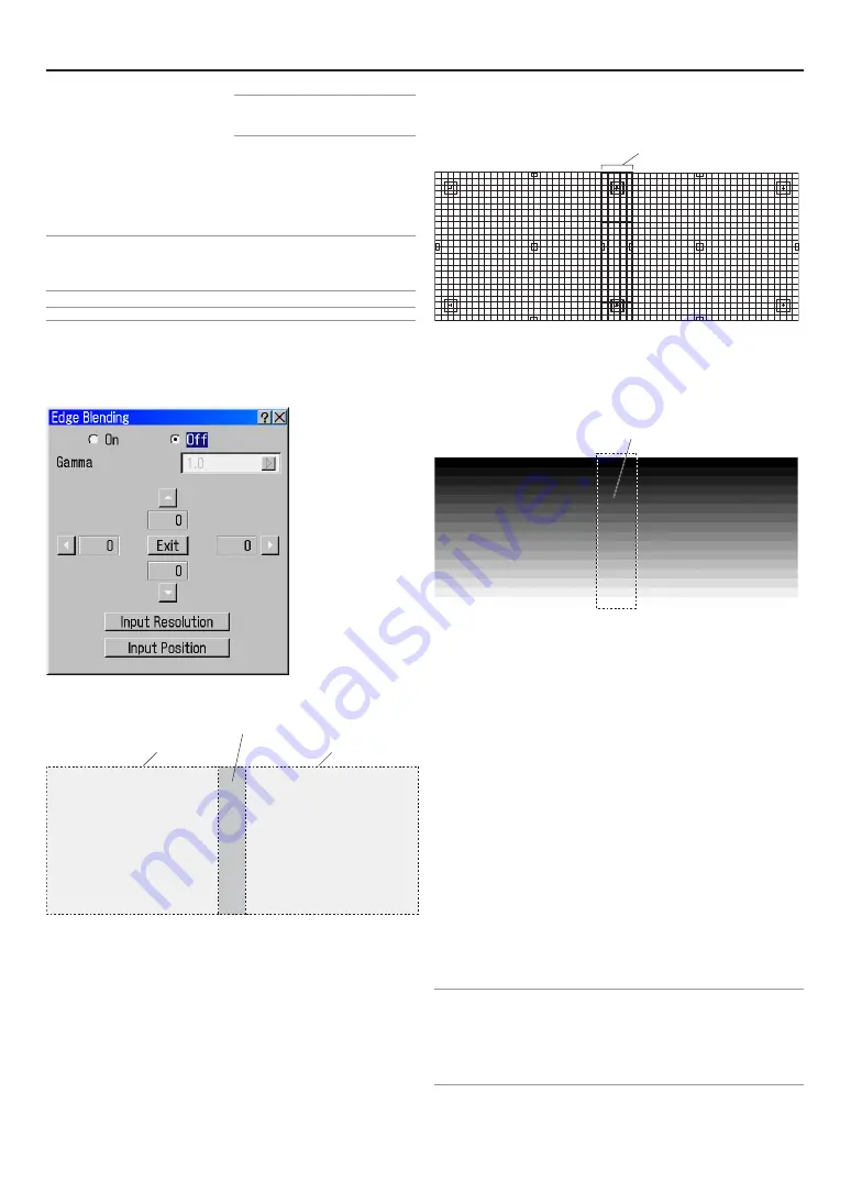
Edge Blending
When two or more projectors are used to project images lined up
horizontally or vertically, a blending adjustment can be performed
to make the borders of the adjacent images less conspicuous.
This description is of an adjustment example in which 2 Projec-
tors are used to project images side-by-side.
Preparation:
Set the lens position of each projector as close to center as pos-
sible.
Making the picture quality of each projector as uniform as pos-
sible will allow the screen edges (boundaries) to be less con-
spicuous.
For good results the Overlapping area should normally be be-
tween 15% and 25% of the image width projectors for landscape
or between 15% to 25% of image height for portrait edge blends.
This may vary depending upon screen size, lens distortion, and
setting of Gamma.
1. Using the test pattern “Cross Hatch” of the Projector, superimpose the
screens so that the height of the 2 projected screens is the same and
the distortion disappears.
2. Select “On” in the “Edge Blending” screen.
• The gamma curve that is adjusted to the input screen can be ad-
justed between 1.0 and 3.0 in steps of 0.1. The gradation expression
of this curve is 8 bits (256 gradations).
• Use the Projector’s test pattern “Horizontal Gray Scale” allows for an
easy adjustment of the gamma curve.
3. From among the 4 locations of “
G
” marks on the “Edge Blending” screen,
move the cursor to the “
G
” mark that is in the same direction as the side
on which you would like to place the blending curve of the projector’s
projection screen.
• Facing the screen, select the “
E
” mark at the left side screen, and
select the “
F
“ mark at the right side screen, then press the ENTER
button.
4. Press the SELECT
G
button of the projector for the left side and move
the adjustment bar so that the adjustment bar fits the left edge of the
right screen which is superimposed on the left side screen.
Determine the blending start position of the left side screen.
• Likewise, operate the Projector of the right side and determine the
blending starting position of the right side screen.
5. Press the “
G
” mark when the adjustment of the blending starting posi-
tion has been completed.
This will exit the adjustment mode.
6. Adjust “Input Resolution” and “Input Position” as required while viewing
the input source and adjust so that the image is superimposed neatly.
7. Select “Adjust (Source)”
→
“Image Options”
→
“Blanking” of the Ad-
vanced Menu and delete the left and right unneeded portions of the
screen as required.
NOTE:
• Edge blending is when SXGA+(1400x1050dots) is displayed in full size, the four
edge lines of screen are the standard (correction range value is 0) position to fix
the blending correction range.
Blending correction can’t be done when projected screen is smaller than full size
screen according to setting of Screen Setup (Page E-56) and Aspect Setup (Page
E-53)
6. Using On-Screen Menu
Projected area
Projected area
Overlapping area
Overlapped cells
Adjust until the boundary area looks seamless and smooth
Summary of Contents for HIGHlite 12000Dsx+
Page 34: ...E 34...
Page 72: ...E 72...
Page 73: ...E 73 7 Maintenance 1 Cleaning the Cabinet and the Lens E 74...
Page 88: ...E 88...
Page 89: ...E 89...
Page 90: ...E 90...


