

Table of Contents
ix
Figure 7–2 SBB Status LEDs .............................................7–3
Figure 7–3 Typical SBB Regulatory Label ........................7–5
Figure 7–4 Typical SBB Bezel Label .................................7–6
Figure 8–1 Enclosure Blower Assemblies Locations ..........8–2
Tables
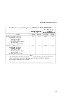
Table 1–1 UltraSCSI Subsystems Capacities ......................1–7
Table 2–1 DIGITAL–Supported Enclosure Address Settings2–6
Table 2–2 Turning Off the DC Power...............................2–10
Table 2–3 Turning On the DC Power ...............................2–11
Table 2–4 Turning Off the Subsystem Power ...................2–12
Table 2–5 Turning On the Subsystem Power ....................2–13
Table 2–6 Enclosure Status Monitoring............................2–14
Table 2–7 Enclosure Status LED Displays .......................2–17
Table 3–1 EMU Communication Cables ............................3–8
Table 3–2 EMU Set Point Temperature Conversions........3–11
Table 3–3 Temperature Set Point Rules............................3–12
Table 3–4 Subsystem Status LEDs Displays.....................3–16
Table 3–5 DC Voltage Ranges .........................................3–17
Table 3–6 EMU Status Displays........................................3–18
Table 3–7 EMU Fault Code Displays ................................3–22
Table 3–8 Removing an EMU ..........................................3–27
Table 3–9 Installing an EMU ..........................................3–27
Table 3–10 EMU Communications Cables .......................3–29
Table 4–1 DC Voltage Ranges ...........................................4–5
Table 4–2 Setting the Enclosure Configuration .................4–6
Table 4–3 DIGITAL Supported Enclosure Addresses.........4–7
Table 4–4 Turning Off the DC Power Distribution ...........4–10
Table 4–5 Turning On the DC Power Distribution............4–10
Table 4–6 Removing a PVA.............................................4–11
Table 4–7 Installing a PVA ..............................................4–12
Table 5–1 TERMPOWER Problems...................................5–6
Table 5–2 UltraSCSI Bus Expansion Rules ........................5–8
Table 5–3 Preliminary Cabling Procedures.........................5–9
Table 5–4 UltraSCSI Bus Cables......................................5–10
Table 5–5 Shutting Down the UltraSCSI Subsystem.........5–11
Table 5–6 Installing Three Enclosure Subsystem Cables ..5–13
Table 5–7 Turning On the UltraSCSI Subsystem..............5–15
Table 5–8 Installing Two Enclosure Subsystem Cables ....5–16
Table 5–9 Removing an I/O Module ................................5–19
Summary of Contents for StorageWorks UltraSCSI DS-BA370 Series
Page 18: ...SES Template Word 7 Blank Page Fix by Peter LaQuerre...
Page 54: ...SES Template Word 7 Blank Page Fix by Peter LaQuerre...
Page 84: ...SES Template Word 7 Blank Page Fix by Peter LaQuerre...
Page 120: ...SES Template Word 7 Blank Page Fix by Peter LaQuerre...
Page 186: ...SES Template Word 7 Blank Page Fix by Peter LaQuerre...


