
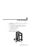
Power Distribution
6–6 UltraSCSI RAID Enclosure
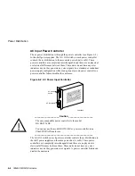
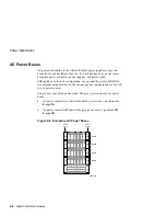
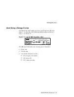
AC Power Buses
AC power distribution to the UltraSCSI shelf power supplies is over two
buses–bus A and bus B (see Figure 6–4). Each bus has an ac power source,
a separate power controller, power supplies, and power cords.
Although bus A, the n+1 configuration, can operate the system, DIGITAL
recommends using both buses, the optimum power configuration (n+4) with
two ac power sources.
Power bus A uses black power cords. The grey power cords are for power
bus B.
•
AC power controller A controls the black power cords—positions 1A
through 5A
•
AC power controller B controls the grey power cords—positions 1B
through 4B
Figure 6–4 Enclosure AC Power Buses
17
11
CXO5808A
19 20
21 22 23 24
13 14
15 16
18
7
8
9
10
12
1
2
3
4
5
6
Controller A
Controller B
EMU
PVA
Cache B
Cache A
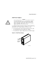
Power
bus A
Power
bus B
A
B
4A
3A
2A
1A
3B
2B
1B
4B
5A
Shelf 4
Shelf 3
Shelf 2
Shelf 1
Summary of Contents for StorageWorks UltraSCSI DS-BA370 Series
Page 18: ...SES Template Word 7 Blank Page Fix by Peter LaQuerre...
Page 54: ...SES Template Word 7 Blank Page Fix by Peter LaQuerre...
Page 84: ...SES Template Word 7 Blank Page Fix by Peter LaQuerre...
Page 120: ...SES Template Word 7 Blank Page Fix by Peter LaQuerre...
Page 186: ...SES Template Word 7 Blank Page Fix by Peter LaQuerre...


