- 106 -
Trip Settings Menu
Trip Settings Menu
is a control menu where certain
protection and auxiliary timer functions, which are
normally expected to give tripping signal to the circuit
breaker, are set to trip the CB or not.
Setting trip functions to
Active
(let CPM 310 G to trip
the CB by that function) or
Passive
(prevent CPM 310 G
to trip the CB by that function) may be needed in many
types of applications, e.g.,
• I>>> and I
e
>>> functions can be set active to
monitor the pick-up current, while their tripping
settings are set to Passive, therefor are not let to trip
the CB. By utilizing this method, it is possible to acquire
information without tripping the CB, whether a device’s
(e.g. an asynchronous motor) pick-up current exceeds
a specified limit,
• A function test of CPM 310 G may be needed to be
conducted online – in this case, setting all parameters
in Trip Settings Menu will do the trick.
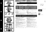
As seen on the pictures to the left, all functions that
normally lead to the tripping of the CB can be
controlled from the menu. The sample picture shows
the default values; with which all protection and
auxiliary timer functions will trip the CB when triggered.
WARNING!
Trip settings are to be modified only by the authorized
personnel; since changes on those settings can prevent
the relay to interrupt faults!
If the settings on the Trip Settings Menu are done
inappropriately, the resulting behavior of the relay may
cause system stresses, failure of fault interrupting,
facility damages, selectivity failures and supply
discontinuity! □
Main Screen » Menu »
Automatic Control Settings »
Trip Settings
Summary of Contents for CPM 310 G
Page 1: ...CPM 310 G Digital Overcurrent Protection Relay User Application Manual vEN 2016 03...
Page 2: ...2...
Page 6: ...6 ABOUT DEMA...
Page 11: ...11 INTRODUCTION...
Page 32: ...32 PACKING LABELING INFORMATION...
Page 34: ...34 OPERATING MANUAL...
Page 53: ...53 RELAY MENUS MANUAL...
Page 55: ...55 The Menu Tree...
Page 56: ...56...
Page 57: ...57...
Page 58: ...58...
Page 59: ...59...
Page 60: ...60...
Page 61: ...61...
Page 128: ...128 DIGICONNECT PC PROGRAM MANUAL...
Page 189: ...189 APPLICATION DIAGRAMS...
Page 191: ...191 Sample Power Transformer Protection Application Diagram...
Page 193: ...193 FUNDAMENTAL CABLING DIAGRAM...
Page 203: ...203 APPLICATION DIAGRAM NO 10 RS485 Cabling...
Page 204: ...204 TECHNICAL DATA...
Page 220: ...220 GLOSSARY...