Chapter 16 PLC Function Applications
│
CFP2000
16-5
16-3 Turn on
16-3-1 Connect to PC
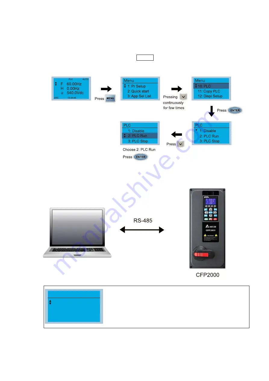
Start operation of PLC functions in accordance with the following four steps
1. After pressing the Menu key and selecting 4: PLC on the KPC-CC01 digital keypad, press
the Enter key (see figure below).
2. Wiring: Connect the drive's RJ45 communications interface to a PC via the RS-485
3. PLC function usage
PLC
1.Disable
2.PLC Run
3.PLC Stop
PLC functions are as shown in the figure on the left; select
item 2 and implement PLC functions.
1: No function (Disable)
2: Enable PLC (PLC Run)
3: Stop PLC functions (PLC Stop)
When the external multifunctional input terminals (MI1–MI8) are in PLC Mode select bit0
(51) or PLC Mode select bit1 (52), and the terminal contact is closed or open, it will
compulsorily switch to the PLC mode, and keypad switching will be ineffective.
Corresponding actions are as follows:
Summary of Contents for CFP2000 Series
Page 3: ......
Page 12: ...Chapter 1 Introduction CFP2000 1 3 1 2 Model Name 1 3 Serial Number ...
Page 15: ...Chapter 1 Introduction CFP2000 1 6 Frame B RFI 1 RFI 1 RFI 1 RFI 2 RFI 2 RFI 2 Figure 1 5 ...
Page 37: ...Chapter 1 Introduction CFP2000 1 28 1 7 Digital Keypad KPC CC01 ...
Page 42: ...Chapter 3 Unpacking CFP2000 3 1 Chapter 3 Unpacking 3 1 Unpacking 3 2 The Lifting Hook ...
Page 54: ...Chapter 4 Wiring CFP2000 4 5 Figure 4 4 ...
Page 57: ...Chapter 4 Wiring CFP2000 4 8 4 4 Basic Waterproof Component Wiring Diagram Frame A Frame B ...
Page 58: ...Chapter 4 Wiring CFP2000 4 9 Frame C D0 ...
Page 75: ...Chapter 5 Main Circuit Terminals CFP2000 5 16 This page intentionally left blank ...
Page 120: ...Chapter 7 Optional Accessories CFP2000 7 35 Wall Mounting Embedded Mounting ...
Page 137: ...Chapter 7 Optional Accessories CFP2000 7 52 This page intentionally left blank ...
Page 173: ...Chapter 9 Specifications CFP2000 9 8 9 5 Efficiency Curve Figure 9 5 ...
Page 251: ...Chapter 11 Summary of Parameter Settings CFP2000 11 42 This page intentionally left blank ...
Page 304: ...Chapter 12 Description of Parameter Settings CFP2000 12 1 03 3 3 4 5 ...
Page 305: ...Chapter 12 Description of Parameter Settings CFP2000 12 1 03 4 6 7 8 ...
Page 306: ...Chapter 12 Description of Parameter Settings CFP2000 12 1 03 5 9 10 11 ...
Page 307: ...Chapter 12 Description of Parameter Settings CFP2000 12 1 03 6 12 13 14 ...
Page 308: ...Chapter 12 Description of Parameter Settings CFP2000 12 1 03 7 15 16 17 ...
Page 309: ...Chapter 12 Description of Parameter Settings CFP2000 12 1 03 8 18 19 20 ...
Page 310: ...Chapter 12 Description of Parameter Settings CFP2000 12 1 03 9 21 22 23 ...
Page 311: ...Chapter 12 Description of Parameter Settings CFP2000 12 1 03 10 24 25 26 ...
Page 312: ...Chapter 12 Description of Parameter Settings CFP2000 12 1 03 11 27 28 29 ...
Page 313: ...Chapter 12 Description of Parameter Settings CFP2000 12 1 03 12 30 31 32 ...
Page 314: ...Chapter 12 Description of Parameter Settings CFP2000 12 1 03 13 33 34 35 ...
Page 315: ...Chapter 12 Description of Parameter Settings CFP2000 12 1 03 14 36 37 38 ...
Page 326: ...Chapter 12 Description of Parameter Settings CFP2000 12 1 03 25 ...
Page 545: ...Chapter 14 Fault Codes and Descriptions CFP2000 14 50 This page intentionally left blank ...
Page 726: ...Chapter 16 PLC Function Applications CFP2000 16 153 ...
Page 728: ...Chapter 16 PLC Function Applications CFP2000 16 155 ...
Page 731: ...Chapter 16 PLC Function Applications CFP2000 16 158 This page intentionally left blank ...
Page 747: ...Chapter 17 Introduction to BACnet CFP2000 17 16 This page intentionally left blank ...


