


SC8000 Controller
Dell Compellent
7
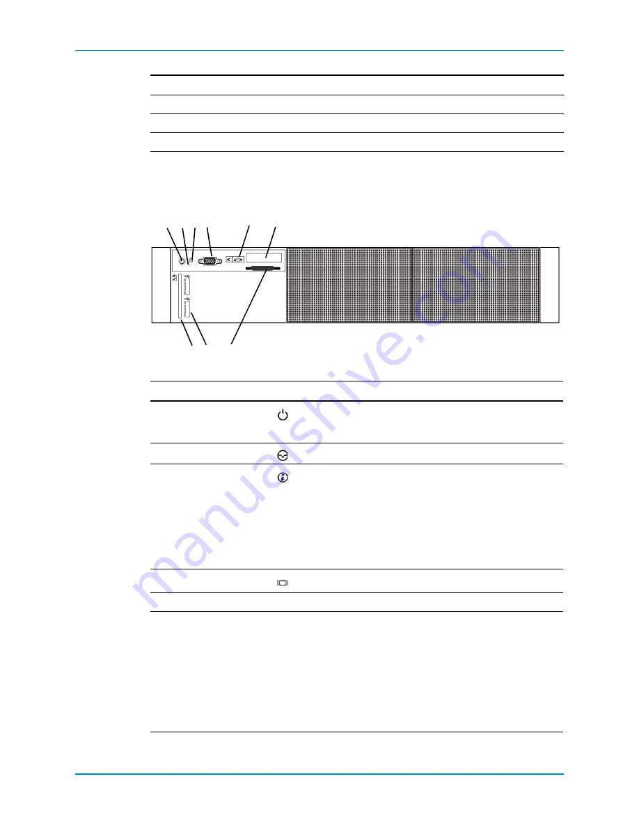
SC8000 Front-Panel Features and Indicators
The
front
panel
of
the
controller
contains
power
and
reset
switches,
and
an
LCD
panel
that
shows
system
ID,
status,
and
error
information.
Figure 4. Front Panel Features and Indicators
Form
Factor
2U
Power
Supplies
2
Fans
6
Item Name
Icon Description
1
Power
‐
on
indicator,
power
button
The
power
‐
on
indicator
is
illuminated
when
the
controller
power
is
powered
on.
The
power
button
controls
the
power
supply
output
to
the
controller.
2
NMI
button
For
the
SC8000,
this
button
is
disabled
in
the
BIOS.
3
System
identification
button
Used
to
locate
a
particular
controller
within
a
rack.
When
a
System
ID
button
on
the
front
or
back
panel
is
pressed,
the
front
LCD
panel
and
the
back
system
status
indicator
flash
until
one
of
the
buttons
is
pressed
again.
• Press
to
toggle
the
system
ID
on
and
off.
• If
the
controller
stops
responding
during
POST,
press
and
hold
the
system
ID
button
for
more
than
five
seconds
to
enter
BIOS
progress
mode.
4
Video
connector
Allows
you
to
connect
a
VGA
monitor
to
the
controller.
5
LCD
menu
buttons
—
Allows
you
to
navigate
the
control
panel
LCD
menu.
6
LCD
panel
—
Displays
system
ID,
status
information,
and
system
error
messages.
• The
LCD
lights
blue
during
normal
controller
operation.
• The
LCD
lights
amber
when
the
controller
needs
attention,
and
the
LCD
panel
displays
an
error
code
followed
by
descriptive
text.
Note:
If
the
controller
is
connected
to
a
power
source
and
an
error
is
detected,
the
LCD
lights
amber
regardless
of
whether
the
controller
is
turned
on
or
off.
Component
Description
2
1
4
6
5
7
8
9
3


