Hard Drives and Media
l
General Information About Hard Drives
l
EIDE Drive Addressing
l
Connecting Drives
Hard Drives
l
Small Form-Factor Desktop System
l
Small Desktop System
l
Small Mini-Tower System
Floppy, Tape, or CD-ROM Drives
l
Small Form-Factor Desktop System
l
Small Desktop System
l
Small Mini-Tower System
General Information About Hard Drives
The small form-factor and small desktop systems support a single enhanced integrated drive electronics (EIDE) hard drive in the hard drive bay;
the small mini-tower system supports two EIDE hard drives.
EIDE Drive Addressing
All EIDE devices require that you configure the cable select setting, which assigns master and slave status to devices according to their position
on the interface cable. You usually configure a drive for cable select by setting a jumper or switch, depending on the drive. Refer to the drive
documentation in your upgrade kit for information on configuring devices for the cable select setting. When you connect two EIDE devices to a
single EIDE interface cable and configure them for the cable select setting, the device attached to the last connector on the interface cable is the
master or boot device (drive 0), and the device attached to the middle connector on the interface cable is the slave device (drive 1).
With the two EIDE interface connectors on the system board, your system supports up to two EIDE devices. EIDE hard drives should be
connected to the EIDE interface connector labeled "IDE1." (Always connect EIDE tape drives and CD-ROM drives to the EIDE interface connector
labeled "IDE2.")
Connecting Drives
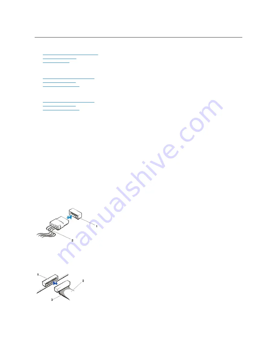
When you install a drive, you connect two cables
—
a DC power cable and an interface cable
—
to the back of the drive. Your drive
’
s power input
connector (to which you connect the DC power cable) resembles the following connector.
Power Cable Connector
The drive
’
s interface connector is a card-edge connector or a header connector, as shown in the following figure.
Drive Interface Connectors
When you attach the interface cable to a drive, be sure to match the colored strip on the cable to pin 1 of the drive
’
s interface connector. For the
location of pin 1 on the drive
’
s interface connector, see the documentation that came with the drive.
When you disconnect an interface cable from the system board, be sure to press in on the locking tabs on the cable connector before you
disconnect the cable. When you attach an interface cable to the system board, be sure that the locking tabs snap into place so that the cable is
1
Power input connector
2
Power cable
1
Header connector
2
Interface cable
3
Colored strip on the cable
Summary of Contents for OptiPlex GX150
Page 2: ...February 2002 08WUP A06 ...
Page 97: ...Back to Contents Page ...


