background image

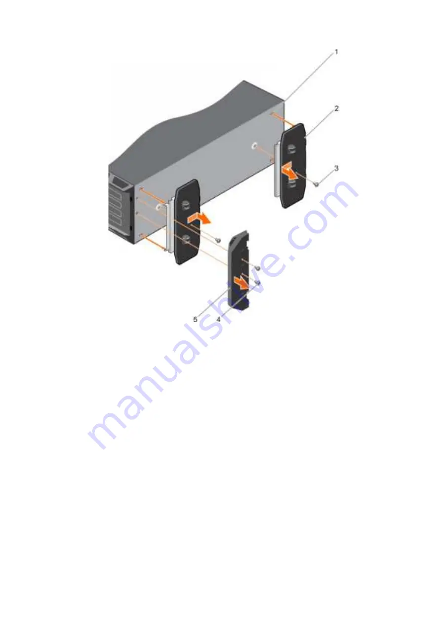
Figure 17. Removing caster wheels

1. slot on base of the tower (4)

2. wheel assembly unit (2)

3. screw for wheel assembly (2)

4. screw for support unit (2)

5. support unit

Related tasks

Installing caster wheels

 on page 56

System cover

The system cover protects the components inside the system and helps in maintaining air flow inside the system. Removing the system
cover activates the intrusion switch.

Removing the system cover

Prerequisites

1. Follow the safety guidelines listed in the Safety instructions section.
2. Turn off the system and any attached peripherals.
3. Disconnect the system from the electrical outlet and peripherals.
4. If installed, remove the front bezel.
5. Place the system on a flat, stable surface.

58

Installing and removing system components

Summary of Contents for E35S001

Page 1: ...Dell PowerEdge T330 Owner s Manual Regulatory Model E35S Series Regulatory Type E35S001 August 2020 Rev A10 ...

Page 2: ......

Page 3: ...abled power supply unit indicator codes 23 Locating service tag of your system 23 Chapter 2 Documentation resources 24 Chapter 3 Technical specifications 26 Chassis dimensions 26 Chassis weight 27 Processor specifications 27 Expansion bus specifications 27 Memory specifications 27 Power specifications 28 Storage controller specifications 28 Drive specifications 28 Hard drives 28 Optical drive 28 T...

Page 4: ...aneous Settings details 46 About Boot Manager 46 Viewing Boot Manager 46 Boot Manager main menu 47 About Dell Lifecycle Controller 47 Changing the boot order 47 Choosing the system boot mode 47 Creating a system or setup password 48 Using your system password to secure your system 48 Deleting or changing system and setup password 49 Operating with a setup password enabled 49 Embedded systems manag...

Page 5: ...er 74 Installing a 2 5 inch hot swappable hard drive into a 3 5 inch hard drive adapter 75 Installing a 3 5 inch hard drive adapter into the 3 5 inch hot swappable hard drive carrier 76 Removing a 3 5 inch hard drive adapter from a 3 5 inch hot swappable hard drive carrier 77 Removing a 2 5 inch hot swappable hard drive from a 3 5 inch hard drive adapter 78 Hard drive backplane 78 Removing the har...

Page 6: ...ontrol panel assembly 124 Installing the control panel assembly 126 Removing the control panel assembly cover 127 Installing the control panel assembly cover 127 Removing the control panel board 128 Installing the control panel board 129 Removing the LCD module 130 Installing the LCD module 131 Removing the optional VGA module 132 Installing the optional VGA module 133 System board 134 Removing th...

Page 7: ...L configuration 152 Troubleshooting iDRAC Direct Laptop connection 152 Troubleshooting a serial input and output device 152 Troubleshooting a NIC 153 Troubleshooting a wet system 153 Troubleshooting a damaged system 154 Troubleshooting the system battery 155 Troubleshooting power supply units 155 Troubleshooting power source problems 155 Power supply unit problems 156 Troubleshooting cooling probl...

Page 8: ...el E3 1200 v5 or v6 series Intel Core i3 6100 series Intel Celeron G3900 series Intel Celeron G3930 Intel Pentium G4500 series Intel Pentium G4600 series Memory modules Up to four DIMMS Hard drives Up to eight hard drives or solid state drives SSDs Topics Supported configurations on PowerEdge T330 systems Front panel Back panel features Diagnostic indicators Locating service tag of your system 1 8...

Page 9: ...Supported configurations on PowerEdge T330 systems Figure 1 System view with supported configurations About the Dell PowerEdge T330 system 9 ...

Page 10: ...e front panel Front panel features and indicators tower mode Figure 2 Front panel features and indicators eight 3 5 inch hot swappable hard drive chassis Table 1 Front panel features and indicators eight 3 5 inch hot swappable hard drive chassis Item Indicator button or connector Icon Description 1 Power on indicator power button Enables you to know the power status of the system The power on indi...

Page 11: ...ponding during POST press and hold the system ID button for more than five seconds to enter BIOS progress mode To reset iDRAC if not disabled in F2 iDRAC setup press and hold the system ID button for more than 15 seconds 4 LCD menu buttons Enable you to navigate the control panel LCD menu 5 Information tag Contains system information such as service tag NIC MAC address and so on for your reference...

Page 12: ...system The power on indicator glows when the system power is on The power button controls the power supply output to the system NOTE On ACPI compliant operating systems turning off the system using the power button causes the system to perform a graceful shutdown before power to the system is turned off 2 NMI button Enables you to troubleshoot software and device driver errors when running certain...

Page 13: ...m information such as service tag NIC MAC address and so on for your reference The information tag is a slide out label panel 6 LCD panel Displays system ID status information and system error messages See LCD panel on page 15 7 USB management port iDRAC Direct port Functions as a regular USB port or provides access to the iDRAC Direct features For more information see the iDRAC Guide at Dell com ...

Page 14: ... or by the operating system documentation 3 System identification button Enables you to locate a particular system within a rack The identification buttons are located on the front and back panels When one of these buttons is pressed the LCD panel on the front and the system status indicator on the back flash until one of the buttons is pressed again Press the system identification button to turn ...

Page 15: ... 5 inch with adapter hot swappable hard drives LCD panel The LCD panel of your system provides system information status and error messages to indicate if the system is functioning correctly or if the system needs attention For more information about error messages see the Dell Event and Error Messages Reference Guide at Dell com openmanagemanuals OpenManage software The LCD backlight turns blue d...

Page 16: ...ected the available fields are IP Subnet Sub and Gateway Gtw Select Setup DNS to enable DNS and to view domain addresses Two separate DNS entries are available Set error Select SEL to view LCD error messages in a format that matches the IPMI description in the SEL This enables you to match an LCD message with an SEL entry Select Simple to view LCD error messages in a simplified user friendly descr...

Page 17: ...e server such as the system identification button power supply sockets cable management arm connectors iDRAC storage media NIC ports and USB and VGA ports A majority of the expansion card ports can be accessed from the back panel The hot swappable power supply units and if installed the rear accessible hard drives are accessible from the back panel Back panel features and indicators Figure 6 Back ...

Page 18: ...ds to enter the BIOS progress mode To reset iDRAC if not disabled in F2 iDRAC setup press and hold for more than 15 seconds 8 System identification connector Enables you to connect the optional system status indicator assembly through the optional cable management arm 9 Video connector Enables you to connect a VGA display to the system 10 Serial connector Enables you to connect a serial device to ...

Page 19: ...es an electrical error for example voltage out of range or a failed power supply unit PSU or voltage regulator Check the System Event Log or system messages for the specific issue If it is due to a problem with the PSU check the LED on the PSU Reseat the PSU If the problem persists see the Getting help section Temperature indicator The indicator flashes amber if the system experiences a thermal er...

Page 20: ... the right side does not turn on Table 7 Hard drive indicator codes Drive status indicator pattern Condition Flashes green twice per second Identifying drive or preparing for removal Off Drive ready for insertion or removal NOTE The drive status indicator remains off until all hard drives are initialized after the system is turned on Drives are not ready for insertion or removal during this time F...

Page 21: ...al Dual SD module IDSDM provides you with a redundant SD card solution You can configure the IDSDM for storage or as the OS boot partition The IDSDM card offers the following features Dual card operation maintains a mirrored configuration by using SD cards in both the slots and provides redundancy NOTE When the Redundancy option is set to Mirror Mode in the Integrated Devices screen of System Setu...

Page 22: ...hes green five times at 4 Hz rate and turns off This indicates that there is a PSU mismatch with respect to efficiency feature set health status and supported voltage CAUTION For AC PSUs use only PSUs with the Extended Power Performance EPP label on the back NOTE Ensure that both the PSUs are of the same capacity NOTE Mixing PSUs from previous generations of Dell PowerEdge servers can result in a ...

Page 23: ... indicator and self diagnostic button 1 self diagnostic button 2 AC PSU status indicator Table 11 Non redundant AC PSU status indicator Power Indicator Pattern Condition Not lit Power is not connected or PSU is faulty Green A valid power source is connected to the PSU and the PSU is operational Locating service tag of your system Your system is identified by a unique Express Service Code and Servi...

Page 24: ...rmation about setting up your system see the Getting Started Guide document that is shipped with your system www dell com poweredgemanuals Configuring your system For information about the iDRAC features configuring and logging in to iDRAC and managing your system remotely see the Integrated Dell Remote Access Controller User s Guide For information about understanding Remote Access Controller Adm...

Page 25: ...troubleshooting Dell OpenManage Enterprise see the Dell OpenManage Enterprise User s Guide www dell com openmanagemanuals OpenManage Enterprise For information about installing and using Dell SupportAssist see the Dell EMC SupportAssist Enterprise User s Guide https www dell com serviceabilitytools For information about partner programs enterprise systems management see the OpenManage Connections ...

Page 26: ...Memory specifications Power specifications Storage controller specifications Drive specifications Ports and connectors specifications Video specifications Expanded operating temperature Environmental specifications Chassis dimensions Figure 11 Chassis dimensions of Dell PowerEdge T330 system 3 26 Technical specifications ...

Page 27: ... Pentium G4500 series Intel Pentium G4600 series Expansion bus specifications PCI Express expansion slots Specification Slot 1 One full height half length x8 PCIe Gen3 card slot connected to processor Slot 2 One full height half length x16 PCIe Gen3 card slot connected to processor Slot 3 One full height half length x1 PCIe Gen3 card slot connected to Platform Controller Hub PCH Slot 4 One full he...

Page 28: ...D S130 and a PERC card For more information on software RAID see the Dell PowerEdge RAID Controller PERC documentation at Dell com storagecontrollermanuals NOTE The upgrade from embedded controller or Software RAID controller to Hardware RAID controller is not supported Drive specifications Hard drives The PowerEdge T330 system supports SAS SATA Nearline SAS hard drives and Solid State Drives SSDs...

Page 29: ...onnector The serial connector connects a serial device to the system The PowerEdge T330 system supports one serial connector on the back panel which is a 9 pin connector Data Terminal Equipment DTE 16550 compliant VGA ports The Video Graphic Array VGA port enables you to connect the system to a VGA display The PowerEdge T330 system supports two 15 pin VGA ports one each on the front and back panel...

Page 30: ...at 5 to 90 RH with 29 C 84 2 F dew point NOTE Outside the standard operating temperature 10 C to 35 C 50 F to 95 F the system can operate down to 5 C 23 F or up to 45 C 113 F for a maximum of 1 of its annual operating hours For temperatures between 40 C 104 F and 45 C 113 F de rate maximum allowable temperature by 1 C per 125 m 33 8 F per 410 105ft above 950 m 3116 8 ft Expanded Operating Temperat...

Page 31: ...rage 12 000 m 39 370 ft Operating temperature de rating Specifications Up to 35 C 95 F Maximum temperature is reduced by 1 C 300 m 33 8 F 984 25 ft above 950 m 3 117 ft 35 C to 40 C 95 F to 104 F Maximum temperature is reduced by 1 C 175 m 1 F 574 14 ft above 950 m 3 117 ft 40 C to 45 C 104 F to 113 F Maximum temperature is reduced by 1 C 125 m 1 F 410 1 ft above 950 m 3 117 ft The following secti...

Page 32: ... Air must be free of corrosive dust Residual dust present in the air must have a deliquescent point less than 60 relative humidity NOTE Applies to data center and non data center environments Gaseous contamination Specifications Copper coupon corrosion rate 300 Å month per Class G1 as defined by ANSI ISA71 04 1985 Silver coupon corrosion rate 200 Å month as defined by AHSRAE TC9 9 NOTE Maximum cor...

Page 33: ...or physical access to the system Options to set up iDRAC IP address You must configure the initial network settings based on your network infrastructure to enable the communication to and from iDRAC You can set up the IP address by using one of the following interfaces Interfaces Document Section iDRAC Settings utility See Dell Integrated Dell Remote Access Controller User s Guide at Dell com idra...

Page 34: ...l PowerEdge systems www dell com ossupport Installation and How to videos for supported operating systems on Dell PowerEdge systems https www youtube com playlist list PLe5xhhyFjDPfTCaDRFflB_VsoLpL8x84G Methods to download firmware and drivers You can download the firmware and drivers by using any of the following methods Table 18 Firmware and drivers Methods Location From the Dell Support site Gl...

Page 35: ...If you do not have the Service Tag select Detect My Product to allow the system to automatically detect your Service Tag or in General support navigate to your product 3 Click Drivers Downloads The drivers that are applicable to your selection are displayed 4 Download the drivers to a USB drive CD or DVD Initial system setup and configuration 35 ...

Page 36: ...he previous field Down arrow Moves to the next field Enter Enables you to type a value in the selected field if applicable or follow the link in the field Spacebar Expands or collapses a drop down list if applicable Tab Moves to the next focus area NOTE This feature is applicable for the standard graphic browser only Esc Moves to the previous page until you view the main screen Pressing Esc in the...

Page 37: ...ription System Information Specifies information about the system such as the system model name BIOS version and Service Tag Memory Settings Specifies information and options related to the installed memory Processor Settings Specifies information and options related to the processor such as speed and cache size SATA Settings Specifies options to enable or disable the integrated SATA controller an...

Page 38: ...mplex programmable logic device CPLD firmware UEFI Compliance Version Specifies the UEFI compliance level of the system firmware Memory Settings details About this task The Memory Settings screen details are explained as follows Option Description System Memory Size Specifies the memory size in the system System Memory Type Specifies the type of memory installed in the system System Memory Speed S...

Page 39: ...Cache Unit DCU IP prefetcher This option is set to Enabled by default Configurable TDP Enables you to reconfigure the processor Thermal Design Power TDP levels during POST based on the power and thermal delivery capabilities of the system TDP verifies the maximum heat the cooling system is needed to dissipate This option is set to Nominal by default NOTE This option is only available on certain st...

Page 40: ...SATA port Capacity Specifies the total capacity of the hard drive This field is undefined for removable media devices such as optical drives Port C For AHCI or RAID mode BIOS support is always enabled Option Description Model Specifies the drive model of the selected device Drive Type Specifies the type of drive attached to the SATA port Capacity Specifies the total capacity of the hard drive This...

Page 41: ...uence Retry Enables or disables the Boot Sequence Retry feature If this option is set to Enabled and the system fails to boot the system reattempts the boot sequence after 30 seconds This option is set to Enabled by default Hard Disk Failover Specifies the hard drive that is booted in the event of a hard drive failure The devices are selected in the Hard Disk Drive Sequence on the Boot Option Sett...

Page 42: ...nternal USB Port Enables or disables the internal USB port This option is set to Enabled by default Integrated Network Card 1 Enables or disables the integrated network card Embedded NIC1 and NIC2 NOTE The Embedded NIC1 and NIC2 options are only available on systems that do not have Integrated Network Card 1 Enables or disables the Embedded NIC1 and NIC2 options If set to Disabled the NIC may stil...

Page 43: ...ame port address for console redirection and the serial device NOTE Every time the system boots the BIOS syncs the serial MUX setting saved in iDRAC The serial MUX setting can independently be changed in iDRAC Loading the BIOS default settings from within the BIOS setup utility may not always revert the serial MUX setting to the default setting of Serial Device 1 External Serial Connector Enables ...

Page 44: ...rgy Efficiency Policy option Energy Efficient Policy Enables you to select the Energy Efficient Policy option The CPU uses the setting to manipulate the internal behavior of the processor and determines whether to target higher performance or better power savings Number of Turbo Boot Enabled Cores for Processor 1 Controls the number of turbo boost enabled cores for processor 1 The maximum number o...

Page 45: ...ined option for AC Power Recovery Delay is selected UEFI Variable Access Provides varying degrees of securing UEFI variables When set to Standard the default UEFI variables are accessible in the operating system per the UEFI specification When set to Controlled selected UEFI variables are protected in the environment and new UEFI boot entries are forced to be at the end of the current boot order S...

Page 46: ...erization This option is set to Disabled by default The two other options are Enabled and Enabled No Reboot NOTE The default setting for In System Characterization is subject to change in future BIOS releases When enabled In System Characterization ISC executes during POST upon detecting relevant changes in system configuration to optimize system power and performance ISC takes about 20 seconds to...

Page 47: ...Boot Mode Steps 1 On the System Setup Main Menu screen click System BIOS Boot Settings 2 Click Boot Option Settings Boot Sequence 3 Use the arrow keys to select a boot device and use the plus and minus sign keys to move the device down or up in the order 4 Click Exit and then click Yes to save the settings on exit Choosing the system boot mode System Setup enables you to specify one of the followi...

Page 48: ...l characters are allowed space A message prompts you to reenter the system password 5 Reenter the system password and click OK 6 In the Setup Password field type your system password and then press Enter or Tab A message prompts you to reenter the setup password 7 Reenter the setup password and click OK 8 Press Esc to return to the System BIOS screen Press Esc again A message prompts you to save t...

Page 49: ...he correct password is typed The following options are exceptions If System Password is not set to Enabled and is not locked through the Password Status option you can assign a system password For more information see the System Security Settings screen section You cannot disable or change an existing system password NOTE You can use the password status option with the setup password option to pro...

Page 50: ...les you to select and customize the thermal control settings for your system 1 Click iDRAC Settings Thermal 2 Under SYSTEM THERMAL PROFILE Thermal Profile select one of the following options Default Thermal Profile Settings Maximum Performance Performance Optimized Minimum Power Performance per Watt Optimized 3 Under USER COOLING OPTIONS set the Fan Speed Offset Minimum Fan Speed and Custom Minimu...

Page 51: ...E Whenever you need to lift the system get others to assist you To avoid injury do not attempt to lift the system by yourself WARNING Opening or removing the system cover while the system is powered on may expose you to a risk of electric shock CAUTION Do not operate the system without the cover for a duration exceeding five minutes CAUTION Many repairs may only be done by a certified service tech...

Page 52: ...lated tasks Removing the optional front bezel on page 53 Removing the system cover on page 58 After working inside your system Steps 1 Install the system cover 2 Place the system upright on its feet on a flat and stable surface 3 Install the optional bezel 4 If applicable install the system into the rack For more information see the Rack installation placemat at Dell com poweredgemanuals 5 Reconne...

Page 53: ...bezel 2 Press the release latch and push the bezel toward the system until the bezel locks into place 3 Lock the bezel by using the key Figure 12 Installing and removing the optional front bezel 1 release latch 2 system 3 bezel key 4 slot on the chassis 2 5 bezel tab 2 6 bezel Removing the optional front bezel Steps 1 Unlock the bezel by using the bezel keys NOTE There are two bezel keys attached ...

Page 54: ...et Prerequisites NOTE It is recommended that you remove the system feet only when you are converting the system from the tower mode to the rack mode or when you are replacing the system feet with the wheel assembly 1 Follow the safety guidelines listed in the Safety instructions section 2 Keep the Phillips 2 screwdriver ready 3 Turn the system feet inward 4 Place the system on its side on a flat a...

Page 55: ...table foundation for the system Failure to install the feet poses the risk of having the system tip over possibly causing bodily injury or damage to the system 1 Follow the safety guidelines listed in the Safety instructions section 2 Keep the Phillips 2 screwdriver ready 3 Place the system on its side on a flat and stable surface Steps 1 Align the tabs on the system feet with the slots on the bas...

Page 56: ...ional Caster wheels provide mobility to the system in the tower mode The caster wheel assembly consists of Caster wheel units front and back Two screws for the caster wheel units Installing caster wheels Prerequisites 1 Follow the safety guidelines listed in the Safety instructions section 2 Keep the Phillips 2 screwdriver ready 3 Place the system on its side on a flat and stable surface with the ...

Page 57: ...mbly 2 Related tasks Removing the system feet on page 54 Removing caster wheels on page 57 Removing caster wheels Prerequisites 1 Follow the safety guidelines listed in the Safety instructions section 2 Keep the Phillips 2 screwdriver ready 3 Place the system on a flat and stable surface with the wheels extending beyond the edge of the surface Steps 1 Remove the screw that secures the front wheel ...

Page 58: ... system and helps in maintaining air flow inside the system Removing the system cover activates the intrusion switch Removing the system cover Prerequisites 1 Follow the safety guidelines listed in the Safety instructions section 2 Turn off the system and any attached peripherals 3 Disconnect the system from the electrical outlet and peripherals 4 If installed remove the front bezel 5 Place the sy...

Page 59: ...ect the system to the electrical outlet 4 Turn the system on including any attached peripherals Related tasks Removing the optional front bezel on page 53 Installing the system cover on page 59 Installing the system cover Prerequisites Ensure that you follow the Safety instructions on page 51 Steps 1 Align the slots on the system cover with the tabs on the chassis 2 Press the cover release latch a...

Page 60: ...s 1 Place the system upright on its feet on a flat and stable surface 2 If removed install the front bezel 3 Reconnect the system to the electrical outlet and peripherals 4 Turn on the system and any attached peripherals Related tasks Installing the optional front bezel on page 53 60 Installing and removing system components ...

Page 61: ...ical drives and tape drives optional Systems with hot swappable hard drives support up to one optical drive and two tape drives NOTE You can also install a Dell PowerVault RD1000 removable media device on your system For systems with hot swappable hard drives the optical and tape drives can be configured as follows Slot 1 SATA optical drive or PowerVault RD1000 Slot 2 PowerVault RD1000 or blank Sl...

Page 62: ... the optical drive or tape drive You must route these cables correctly and in a similar manner when you replace them to prevent them from being pinched or crimped 2 If required disconnect the power cable from the backplane and disconnect the data cable from the system board 3 Press the release latch in the direction of the arrow 4 Slide the optical drive or tape drive out of the drive bay 5 If you...

Page 63: ... or tape drive on page 63 Installing the optical drive or tape drive Prerequisites CAUTION Many repairs may only be done by a certified service technician You should only perform troubleshooting and simple repairs as authorized in your product documentation or as directed by the online or telephone service and support team Damage due to servicing that is not authorized by Dell is not covered by yo...

Page 64: ...e bay 4 Slide the optical drive or tape drive into the slot until the optical drive or tape drive snaps into place 5 Connect the power and data cables to the back of the optical drive or tape drive 6 Connect the power cable to the backplane and connect the data cable to the system board Figure 23 Installing the optical drive or tape drive a optical drive or tape drive b guide c release latch Next ...

Page 65: ...authorized by Dell is not covered by your warranty Read and follow the safety instructions that are shipped with your product CAUTION Never operate your system with the air shroud removed The system may get overheated quickly resulting in shutdown of the system and loss of data 1 Ensure that you follow the Safety instructions on page 51 2 Follow the procedure listed in Before working inside your s...

Page 66: ...e your system section CAUTION Do not operate the system with the cover removed for a duration exceeding 5 minutes NOTE For proper seating of the cooling shroud in the system chassis ensure that the cables inside the system are routed along the chassis wall and secured using the cable securing clips Steps 1 Align the slots on the cooling shroud with the tabs on the internal cooling fan 2 Lower the ...

Page 67: ...ot authorized by Dell is not covered by your warranty Read and follow the safety instructions that are shipped with your product 1 Ensure that you follow the Safety instructions on page 51 2 Follow the procedure listed in Before working inside your system on page 52 3 Remove the cooling shroud Steps 1 Disconnect the intrusion switch cable from the intrusion switch connector on the system board 2 P...

Page 68: ...vice and support team Damage due to servicing that is not authorized by Dell is not covered by your warranty Read and follow the safety instructions that are shipped with your product 1 Ensure that you follow the Safety instructions on page 51 2 Follow the procedure listed in Before working inside your system on page 52 Steps 1 Slide the intrusion switch into the intrusion switch slot 2 Connect th...

Page 69: ...kplane When you format a hard drive allow enough time for the formatting to be completed Be aware that high capacity hard drives can take a long time to format Supported hard drive configurations Depending on the configuration your system supports one of the following Four hard drive systems Up to four 3 5 inch 2 5 inch with adapter hot swappable SAS SATA and nearline SAS hard drives solid state d...

Page 70: ...y be done by a certified service technician You should only perform troubleshooting and simple repairs as authorized in your product documentation or as directed by the online or telephone service and support team Damage due to servicing that is not authorized by Dell is not covered by your warranty Read and follow the safety instructions that came with the product 1 Follow the safety guidelines l...

Page 71: ...ard drive is online the green activity or fault indicator flashes when the hard drive is turned off You can remove the hard drive when the hard drive indicators turn off CAUTION To prevent data loss ensure that your operating system supports hot swap drive installation See the documentation supplied with your operating system NOTE Hot swappable hard drives are supplied in hot swappable hard drive ...

Page 72: ...rive carrier Prerequisites CAUTION Many repairs may only be done by a certified service technician You should only perform troubleshooting and simple repairs as authorized in your product documentation or as directed by the online or telephone service and support team Damage due to servicing that is not authorized by Dell is not covered by your warranty Read and follow the safety instructions that...

Page 73: ...tation or as directed by the online or telephone service and support team Damage due to servicing that is not authorized by Dell is not covered by your warranty Read and follow the safety instructions that are shipped with your product NOTE Hot swappable hard drives are supplied in hot swappable hard drive carriers that fit in the hard drive slots 1 Keep the Phillips 2 screwdriver ready 2 Remove t...

Page 74: ...acement hot swappable drive is installed and the system is powered on the drive automatically begins to rebuild Ensure that the replacement drive is blank or contains data that you wish to overwrite Any data on the replacement drive is immediately lost after the drive is installed NOTE Hot swappable hard drives are supplied in hot swappable hard drive carriers that fit in the hard drive slots 1 If...

Page 75: ...perform troubleshooting and simple repairs as authorized in your product documentation or as directed by the online or telephone service and support team Damage due to servicing that is not authorized by Dell is not covered by your warranty Read and follow the safety instructions that are shipped with your product 1 Follow the safety guidelines listed in the Safety instructions section 2 Keep the ...

Page 76: ...ce and support team Damage due to servicing that is not authorized by Dell is not covered by your warranty Read and follow the safety instructions that are shipped with your product 1 Follow the safety guidelines listed in the Safety instructions section 2 Keep the Phillips 2 screwdriver ready 3 Install the 2 5 inch hot swappable hard drive into the 3 5 inch hard drive adapter Steps 1 Insert the 3...

Page 77: ...er from a 3 5 inch hot swappable hard drive carrier Prerequisites 1 Follow the safety guidelines listed in the Safety instructions section 2 Keep the Phillips 2 screwdriver ready 3 Remove the 3 5 inch hot swappable hard drive carrier from the system Steps 1 Remove the screws from the rails on the 3 5 inch hot swappable hard drive carrier 2 Lift the 3 5 inch hard drive adapter out of the 3 5 inch h...

Page 78: ...e Safety instructions section 2 Keep the Phillips 2 screwdriver ready 3 Remove the 3 5 inch hard drive adapter from the 3 5 inch hot swappable hard drive carrier NOTE A 2 5 inch hot swappable hard drive is installed in a 3 5 inch hard drive adapter which is then installed in the 3 5 inch hot swappable hard drive carrier Steps 1 Remove the screws from the side of the 3 5 inch hard drive adapter 2 R...

Page 79: ...safety instructions that are shipped with your product 1 Ensure that you follow the Safety instructions on page 51 2 Follow the procedure listed in Before working inside your system on page 52 CAUTION To prevent damage to the drives and backplane remove the hard drives from the system before removing the backplane CAUTION Note the slot number of each hard drive and temporarily label the slots befo...

Page 80: ...ector 3 backplane power connector 4 backplane signal connector 5 SAS A connector 6 SAS B connector Figure 40 Cabling x8 hard drive backplane with PERC card and SAS HBA 1 PERC card 2 SAS tape drive connector on SAS HBA 3 SAS Host Bus Adapter HBA 4 system board 80 Installing and removing system components ...

Page 81: ... hard drive backplane 6 SAS A connector on backplane 7 optical disk drive or SATA tape drive 8 optical disk drive Next steps 1 Install the hard drive backplane 2 Follow the procedure listed in After working inside your system on page 52 Related tasks Removing a hot swappable hard drive carrier on page 71 Installing the hard drive backplane on page 81 Installing the hard drive backplane Prerequisit...

Page 82: ... backplane 2 Slide down the hard drive backplane until the release pin locks into the slot 3 Connect the SAS power and data cables to the hard drive backplane Figure 42 Installing an x8 hard drive backplane 1 SAS cable 2 x8 hard drive backplane 3 power connector 4 backplane power cable 5 optical disk drive power cable 6 release pin 7 signal cable Next steps 1 Install the hard drives in their origi...

Page 83: ...the hard drives and backplane you must remove the hard drives from the system before removing the backplane CAUTION Note the slot number of each hard drive and temporarily label the slots before removing the hard drives so that you can replace them in the same location s 3 Remove the cooling shroud 4 Remove all hard drives 5 Remove the x8 hard drive backplane Steps 1 Using a screwdriver push the r...

Page 84: ...elines listed in the Safety instructions section 2 Follow the procedure listed in the Before working inside your system section Steps 1 Locate the hard drive slots numbered from four to seven 2 Insert the four slot hard drive blank into the hard drive slot and push it until the release tabs click into place Figure 44 Installing the four slot hard drive blank a four slot hard drive blank b release ...

Page 85: ...kets each Each 2 socket set is organized into one channel In each 2 socket set the first socket release lever is marked white and the second socket release lever is marked black Figure 45 Memory socket locations on the system board Memory channels are organized as follows Processor 1 channel 0 memory sockets A1 and A3 channel 1 memory sockets A2 and A4 The following table shows the memory populati...

Page 86: ...other memory population rules are followed for example 4 GB and 8 GB memory modules can be mixed Mixing of more than two DIMM capacities in a system is not supported Populate two DIMMs per processor one DIMM per channel at a time to maximize performance Sample memory configurations The following table shows sample memory configurations for a single processor configuration NOTE 1R and 2R in the fol...

Page 87: ...that you follow the Safety instructions on page 51 2 Follow the procedure listed in Before working inside your system on page 52 3 Remove the cooling shroud NOTE The memory modules are hot to touch for some time after the system has been powered down Allow the memory modules to cool before handling them Handle the memory modules by the card edges and avoid touching the components or metallic conta...

Page 88: ...vered by your warranty Read and follow the safety instructions that are shipped with your product 1 Ensure that you follow the Safety instructions on page 51 2 Follow the procedure listed in Before working inside your system on page 52 3 Remove the cooling shroud NOTE The memory modules are hot to touch for some time after the system has been powered down Allow the memory modules to cool before ha...

Page 89: ...dure listed in After working inside your system on page 52 3 Press F2 to enter System Setup and check the System Memory setting The System Memory Size should reflect the installed memory 4 If the value is incorrect one or more of the memory modules may not be installed properly Ensure that the memory modules are firmly seated in the sockets 5 Run the system memory test in system diagnostics See De...

Page 90: ...repairs may only be done by a certified service technician You should only perform troubleshooting and simple repairs as authorized in your product documentation or as directed by the online or telephone service and support team Damage due to servicing that is not authorized by Dell is not covered by your warranty Read and follow the safety instructions that are shipped with your product CAUTION D...

Page 91: ...certified service technician You should only perform troubleshooting and simple repairs as authorized in your product documentation or as directed by the online or telephone service and support team Damage due to servicing that is not authorized by Dell is not covered by your warranty Read and follow the safety instructions that are shipped with your product 1 Follow the safety guidelines listed i...

Page 92: ... Processor Connection Height Length Link Width Slot Width 1 Processor Full Height Half Length x4 x8 2 Processor Full Height Half Length x8 x16 3 Platform Controller Hub Full Height Half Length x1 x1 4 Platform Controller Hub Full Height Half Length x4 x8 NOTE All slots support Generation 3 PCIe expansion cards NOTE The expansion cards are not hot swappable The following table provides a guide for ...

Page 93: ...service and support team Damage due to servicing that is not authorized by Dell is not covered by your warranty Read and follow the safety instructions that are shipped with your product 1 Follow the safety guidelines listed in the Safety instructions section 2 Follow the procedure listed in the Before working inside your system section 3 Remove the cooling shroud 4 Disconnect the cables from the ...

Page 94: ...pansion card latch b expansion card c expansion card connector Figure 51 Removing the filler bracket 1 expansion card latch 2 slot 3 filler bracket 4 guide pin Next steps 1 Install an expansion card 94 Installing and removing system components ...

Page 95: ...n 3 Remove the cooling shroud 4 Disconnect the cables from the expansion card Steps 1 Unpack the expansion card and prepare it for installation For instructions see the documentation accompanying the card 2 Open the expansion card latch for the slot in which you want to install the expansion card 3 If you are installing a new card slide the filler bracket out of the system NOTE Store the filler br...

Page 96: ... Installing an expansion card a expansion card latch b expansion card connector c expansion card Figure 53 Installing the filler bracket 1 expansion card latch 2 slot 96 Installing and removing system components ...

Page 97: ...Controller User s Guide at Dell com idracmanuals Removing the optional SD vFlash card Prerequisites 1 Follow the safety guidelines listed in the Safety instructions section 2 Locate the SD vFlash card slot at the back of the chassis Steps To remove the SD vFlash card push the SD vFlash card inward to release it and pull the SD vFlash card from the SD vFlash card slot Figure 54 Removing the optiona...

Page 98: ... local storage and a custom deployment environment that enables automation of server configuration scripts and imaging It emulates a USB device For more information see the Integrated Dell Remote Access Controller User s Guide at Dell com idracmanuals Removing the optional iDRAC port card Prerequisites CAUTION Many repairs may only be done by a certified service technician You should only perform ...

Page 99: ... the cooling shroud on page 65 Removing the internal cooling fan on page 90 Installing the optional iDRAC port card on page 99 Installing the internal cooling fan on page 90 Installing the cooling shroud on page 66 Installing the optional iDRAC port card Prerequisites CAUTION Many repairs may only be done by a certified service technician You should only perform troubleshooting and simple repairs ...

Page 100: ... and insert the tabs on the iDRAC port card on the slots on the chassis wall 2 Insert the iDRAC port card into the connector on the system board 3 Tighten the screw to secure the iDRAC port card Figure 57 Installing the iDRAC port card 1 iDRAC port 2 SD vFlash media card 3 iDRAC port card connector 4 iDRAC port card holder 5 captive screw 2 Next steps 1 Reconnect all the cables to the iDRAC port c...

Page 101: ...ed service technician You should only perform troubleshooting and simple repairs as authorized in your product documentation or as directed by the online or telephone service and support team Damage due to servicing that is not authorized by Dell is not covered by your warranty Read and follow the safety instructions that are shipped with your product 1 Follow the safety guidelines listed in the S...

Page 102: ...team Damage due to servicing that is not authorized by Dell is not covered by your warranty Read and follow the safety instructions that are shipped with your product 1 Follow the safety guidelines listed in the Safety instructions section 2 Follow the procedure listed in the Before working inside your system section 3 Ensure that the Internal SD Card Port option is set to Enabled in System Setup ...

Page 103: ...rected by the online or telephone service and support team Damage due to servicing that is not authorized by Dell is not covered by your warranty Read and follow the safety instructions that are shipped with your product 1 Follow the safety guidelines listed in the Safety instructions section 2 Follow the procedure listed in the Before working inside your system section 3 Locate the Internal Dual ...

Page 104: ...y perform troubleshooting and simple repairs as authorized in your product documentation or as directed by the online or telephone service and support team Damage due to servicing that is not authorized by Dell is not covered by your warranty Read and follow the safety instructions that are shipped with your product 1 Follow the safety guidelines listed in the Safety instructions section 2 Follow ...

Page 105: ...oduct documentation or as directed by the online or telephone service and support team Damage due to servicing that is not authorized by Dell is not covered by your warranty Read and follow the safety instructions that are shipped with your product CAUTION Never remove the heat sink from a processor unless you intend to remove the processor The heat sink is necessary to maintain proper thermal con...

Page 106: ...are removing only a faulty heat sink install the replacement heat sink if not remove the processor 2 Follow the procedure listed in the After working inside your system section Related tasks Removing the cooling shroud on page 65 Installing the heat sink on page 110 Installing the processor on page 108 Installing the cooling shroud on page 66 Removing the processor Prerequisites CAUTION Many repai...

Page 107: ...ow the processor to cool before removing it CAUTION The processor is held in its socket under strong pressure Be aware that the release lever can spring up suddenly if not firmly held Steps 1 Release the socket lever by pushing the lever down and out from under the tab on the processor shield 2 Lift the lever upward until the processor shield lifts CAUTION The processor socket pins are fragile and...

Page 108: ...n page 66 Installing the processor Prerequisites CAUTION Many repairs may only be done by a certified service technician You should only perform troubleshooting and simple repairs as authorized in your product documentation or as directed by the online or telephone service and support team Damage due to servicing that is not authorized by Dell is not covered by your warranty Read and follow the sa...

Page 109: ...ntaminants on the processor contacts such as thermal grease or oil can damage the processor 3 Align the processor with the socket keys CAUTION Do not use force to seat the processor When the processor is positioned correctly it engages easily into the socket CAUTION Positioning the processor incorrectly can permanently damage the system board or the processor Be careful not to bend the pins in the...

Page 110: ...tly Related tasks Removing the cooling shroud on page 65 Installing the cooling shroud on page 66 Removing the processor on page 106 Installing the heat sink on page 110 Installing the heat sink Prerequisites CAUTION Many repairs may only be done by a certified service technician You should only perform troubleshooting and simple repairs as authorized in your product documentation or as directed b...

Page 111: ...ispose of the syringe after you use it Figure 67 Applying thermal grease on the top of the processor a processor b thermal grease c thermal grease syringe 3 Place the heat sink onto the processor 4 Tighten one of the four screws to secure the heat sink to the system board 5 Tighten the screw diagonally opposite to the first screw you tightened NOTE Do not overtighten the heat sink retention screws...

Page 112: ...e output state If having both PSUs active is more efficient than having one PSU in the sleep state the active PSU can also activate the sleeping PSU The default PSU settings are as follows If the load on the active PSU is more than 50 percent then the redundant PSU is switched to the active state If the load on the active PSU falls below 20 percent then the redundant PSU is switched to the sleep s...

Page 113: ...ould only perform troubleshooting and simple repairs as authorized in your product documentation or as directed by the online or telephone service and support team Damage due to servicing that is not authorized by Dell is not covered by your warranty Read and follow the safety instructions that are shipped with your product 1 Follow the safety guidelines listed in the Safety instructions section 2...

Page 114: ... a new PSU in a system with two PSUs allow several seconds for the system to recognize the PSU and determine its status The PSU status indicator turns green to signify that the PSU is functioning properly Removing the power supply unit blank Prerequisites Ensure that you follow the Safety instructions on page 51 Steps If you are installing a second power supply unit PSU remove the PSU blank in the...

Page 115: ...power supply unit PSU blank only in the second PSU bay Prerequisites CAUTION To ensure proper system cooling the PSU blank must be installed in the second PSU bay in a non redundant configuration Remove the PSU blank only if you are installing a second PSU Steps Align the PSU blank with the PSU bay and push the PSU blank into the chassis until it clicks into place Installing and removing system co...

Page 116: ...urn off the system including any attached peripherals and disconnect the system from the electrical outlet and peripherals 2 If installed remove the redundant power supply units PSUs or PSU blank Steps 1 Remove the screw that secures the PSU divider to the chassis 2 Slide out the PSU divider and turn it clockwise to free the tabs on the PSU divider from the slots on the PSU cage 3 Slide the PSU di...

Page 117: ...tion verify the system power consumption with the Dell Energy Smart Solution Advisor at Dell com ESSA to ensure optimum power utilization Removing a cabled power supply unit Prerequisites CAUTION Many repairs may only be done by a certified service technician You should only perform troubleshooting and simple repairs as authorized in your product documentation or as directed by the online or telep...

Page 118: ... cable connector 7 P1 power cable connector 8 P4 backplane connector Next steps 1 Install a cabled PSU 2 Follow the procedure listed in the After working inside your system section Related tasks Installing a cabled power supply unit on page 118 Installing a cabled power supply unit Prerequisites CAUTION Many repairs may only be done by a certified service technician You should only perform trouble...

Page 119: ...e until the PSU is fully seated 2 Tighten the screw to secure the PSU to the chassis 3 Connect all the power cables from the PSU to the system board hard drive backplane hard drives and optical drives Figure 74 Installing a cabled PSU 1 screw 2 PSU cage 3 non redundant PSU 4 standoff on the chassis 5 P2 power cable connector 6 P1 signal cable connector 7 P1 power cable connector 8 P4 backplane con...

Page 120: ...ith your product 1 Follow the safety guidelines listed in the Safety instructions section 2 Follow the procedure listed in the Before working inside your system section CAUTION To prevent damage to the power interposer board you must remove the power supply units PSUs or PSU blank from the system before removing the power interposer board PIB 3 Remove the PSUs or PSU blanks from the back of the ch...

Page 121: ...roubleshooting and simple repairs as authorized in your product documentation or as directed by the online or telephone service and support team Damage due to servicing that is not authorized by Dell is not covered by your warranty Read and follow the safety instructions that are shipped with your product Follow the safety guidelines listed in the Safety instructions section Steps 1 Align the slot...

Page 122: ...oling shroud on page 66 Installing the power supply unit blank on page 115 System battery The system battery is used to power the real time clock and storing the BIOS settings of the system Replacing the system battery Prerequisites 1 Follow the safety guidelines listed in safety instructions section 2 Follow the procedure listed in the Before working in your system section 3 Remove the cooling sh...

Page 123: ...ld Replaceable Unit FRU Removal and installation procedures must be performed only by Dell certified service technicians Steps 1 Locate the battery socket For more information see the System board connectors section CAUTION To avoid damage to the battery connector you must firmly support the connector while installing or removing a battery 2 Use a plastic scribe to pry out the system battery as sh...

Page 124: ...r telephone service and support team Damage due to servicing that is not authorized by Dell is not covered by your warranty Read and follow the safety instructions that are shipped with your product 1 Follow the safety guidelines listed in the Safety instructions section 2 Keep the Phillips 2 screwdriver ready 3 Follow the procedure listed in the Before working inside your system section 4 Remove ...

Page 125: ... information tag to replace it in the new control panel Figure 80 Removing and installing the information tag a information tag b tab 2 c slot Next steps 1 Install the control panel assembly 2 Follow the procedure listed in the After working inside your system section Related tasks Preparing a system for conversion from tower mode to rack mode on page 143 Removing the optional optical drive or tap...

Page 126: ... with the information tag retained from the old control panel NOTE Information tag lists system information such as Service Tag NIC MAC address 2 To install the information tag push the information tag into the control panel slot 3 Connect the control panel cable and the control panel USB cable to the control panel module 4 Align and insert the control panel into the control panel slot in the chas...

Page 127: ... assembly Steps 1 Unhook the tab adjacent to the power button 2 Unhook the tab on the bottom of the control panel assembly cover 3 Pull the control panel assembly cover to detach it from the control panel Figure 82 Removing the control panel assembly cover for system with LCD panel Next steps 1 Install the control panel assembly cover 2 Follow the procedure listed in the After working inside your ...

Page 128: ...uisites CAUTION Many repairs may only be done by a certified service technician You should only perform troubleshooting and simple repairs as authorized in your product documentation or as directed by the online or telephone service and support team Damage due to servicing that is not authorized by Dell is not covered by your warranty Read and follow the safety instructions that are shipped with y...

Page 129: ...and support team Damage due to servicing that is not authorized by Dell is not covered by your warranty Read and follow the safety instructions that are shipped with your product 1 Follow the safety guidelines listed in the Safety instructions section 2 Follow the procedure listed in the Before working inside your system section 3 Keep the Phillips 2 screwdriver ready Steps 1 Align the control pan...

Page 130: ...eam Damage due to servicing that is not authorized by Dell is not covered by your warranty Read and follow the safety instructions that are shipped with your product 1 Follow the safety guidelines listed in the Safety instructions section 2 Keep the Phillips 2 screwdriver ready 3 Follow the procedure listed in the Before working inside your system section 4 Remove the control panel assembly 5 Remo...

Page 131: ...documentation or as directed by the online or telephone service and support team Damage due to servicing that is not authorized by Dell is not covered by your warranty Read and follow the safety instructions that are shipped with your product 1 Follow the safety guidelines listed in the Safety instructions section 2 Follow the procedure listed in the Before working inside your system section 3 Kee...

Page 132: ...optional VGA module Prerequisites CAUTION Many repairs may only be done by a certified service technician You should only perform troubleshooting and simple repairs as authorized in your product documentation or as directed by the online or telephone service and support team Damage due to servicing that is not authorized by Dell is not covered by your warranty Read and follow the safety instructio...

Page 133: ...service technician You should only perform troubleshooting and simple repairs as authorized in your product documentation or as directed by the online or telephone service and support team Damage due to servicing that is not authorized by Dell is not covered by your warranty Read and follow the safety instructions that are shipped with your product 1 Follow the safety guidelines listed in the Safe...

Page 134: ... the system board Prerequisites CAUTION Many repairs may only be done by a certified service technician You should only perform troubleshooting and simple repairs as authorized in your product documentation or as directed by the online or telephone service and support team Damage due to servicing that is not authorized by Dell is not covered by your warranty Read and follow the safety instructions...

Page 135: ...hroud b memory modules c cooling fan d expansion cards e heat sink and processor f iDRAC port card if installed g internal dual SD module if installed Steps 1 Disconnect all cables from the system board CAUTION Take care not to damage the system identification button while removing the system board from the chassis 2 Remove the screws on the system board and slide the system board toward the front...

Page 136: ...g the processor on page 106 Removing the optional iDRAC port card on page 98 Removing the optional internal dual SD module on page 103 Installing the system board Prerequisites CAUTION Many repairs may only be done by a certified service technician You should only perform troubleshooting and simple repairs as authorized in your product documentation or as directed by the online or telephone servic...

Page 137: ... the Phillips 2 screwdriver ready Steps 1 Hold the system board by its edges and orient it toward the back of the chassis 2 Lower the system board into the chassis until the connectors at the back of the system board align with the slots on the back of the chassis 3 Tighten the screws that secure the system board to the chassis Figure 92 Install the system board a system board b touch point 2 c sy...

Page 138: ...lling the internal cooling fan on page 90 Installing the cooling shroud on page 66 Installing the optional iDRAC port card on page 99 Installing the optional internal dual SD module on page 104 Restoring the Service Tag by using the Easy Restore feature By using the Easy Restore feature you can restore your Service Tag license UEFI configuration and the system configuration data after replacing th...

Page 139: ...yptographic binding and it cannot be re installed or installed on another system board NOTE This is a Field Replaceable Unit FRU Removal and installation procedures must be performed only by Dell certified service technicians Installing the Trusted Platform Module Prerequisites CAUTION Many repairs may only be done by a certified service technician You should only perform troubleshooting and simpl...

Page 140: ...s to Enabled Activated Initializing the TPM for TXT users Steps 1 While booting your system press F2 to enter System Setup 2 On the System Setup Main Menu screen click System BIOS System Security Settings 3 From the TPM Security option select On with Pre boot Measurements 4 From the TPM Command option select Activate 5 Save the settings 6 Restart your system 7 Enter System Setup again 8 On the Sys...

Page 141: ...eripherals and disconnect the system from the electrical outlet and peripherals 4 Remove the system cover Steps 1 Remove the screws that secure the top cover to the chassis 2 Slide the cover toward the back of the system and lift it from the system Figure 94 Removing the system top cover a system top cover b screw 3 Related tasks Removing the system cover on page 58 Installing the system top cover...

Page 142: ...under the top cover with the slots on the top of the chassis 2 Slide the cover toward the front of the system until the screw holes on the cover align with the screw holes on the chassis 3 Tighten the screws to secure the cover onto the chassis Figure 95 Installing the system top cover a system top cover b screw 3 Next steps 1 Install the system cover 2 Reconnect the system to its electrical outle...

Page 143: ...y customers certified by Dell for tower to rack conversion can convert a tower system into a rack system NOTE For specific caution statements and procedures see the rack installation documentation for your system at Dell com poweredgemanuals For complete safety and regulatory information see the safety instructions that shipped with your system Observe the following precautions for stability and s...

Page 144: ... 96 Removing and installing the rack ears i front panel ii rack ear 2 iii screw for each rack ear 3 Next steps 1 Install the system cover 2 Install the system in a rack For more information see the system s Rack Installation Guide at Dell com poweredgemanuals Related tasks Removing the system feet on page 54 Removing caster wheels on page 57 Removing the system cover on page 58 Removing the contro...

Page 145: ...lowing you to Run tests automatically or in an interactive mode Repeat tests Display or save test results Run thorough tests to introduce additional test options to provide extra information about the failed device s View status messages that inform you if tests are completed successfully View error messages that inform you of problems encountered during testing When to use the Embedded System Dia...

Page 146: ...System diagnostics controls Menu Description Configuration Displays the configuration and status of all detected devices Results Displays the results of all tests that are executed System health Provides the current overview of the system performance Event log Displays a time stamped log of the results of all tests run on the system This is displayed if at least one event description is recorded 1...

Page 147: ...rs Figure 97 System board jumpers and connectors Table 24 System board jumpers and connectors Ite m Connector Description 1 Slot 1 PCIE_G3_X4 CPU PCIe card connector 1 2 Slot 2 PCIE_G3_X8 CPU PCIe card connector 2 3 Slot 3 PCIE_G3_X1 PCH PCIe card connector 3 4 INT_USB_3 0 Internal USB 5 Slot 4 PCIE_G3_X4 PCH PCIe card connector 4 9 Jumpers and connectors 147 ...

Page 148: ...L Control panel 26 BATTERY System battery System board jumper settings CAUTION Many repairs may only be done by a certified service technician You should only perform troubleshooting and simple repairs as authorized in your product documentation or as directed by the online or telephone service and support team Damage due to servicing that is not authorized by Dell is not covered by your warranty ...

Page 149: ...er 3 Move the jumper on the system board jumper from pins 2 and 3 to pins 1 and 2 4 Install the system cover The existing passwords are not disabled erased until the system boots with the jumper on pins 1 and 2 However before you assign a new system and or setup password you must move the jumper back to pins 2 and 3 NOTE If you assign a new system and or setup password with the jumper on pins 1 an...

Page 150: ...roblems Troubleshooting cooling fans Troubleshooting system memory Troubleshooting an internal USB key Troubleshooting a micro SD card Troubleshooting an optical drive Troubleshooting a tape backup unit Troubleshooting a drive or SSD Troubleshooting a storage controller Troubleshooting expansion cards Troubleshooting processors Troubleshooting system startup failure If you boot the system to the B...

Page 151: ...Utility ensure that USB Management Port Mode is configured as Automatic or Standard OS Use 5 If the problem is not resolved replace the keyboard and or mouse with a known working keyboard or mouse If the problem is not resolved proceed to step 6 to troubleshoot other USB devices attached to the system If the problem is not resolved proceed to troubleshoot other USB devices attached to the system 6...

Page 152: ...oting iDRAC Direct Laptop connection For information about USB laptop connection and system configuration see the Integrated Dell Remote Access Controller User s Guide at www dell com poweredgemanuals Steps 1 Ensure that your laptop is connected to the front USB Management Port identified by icon with a USB Type A A cable 2 On the iDRAC Settings Utility screen ensure that USB Management Port Mode ...

Page 153: ...re set to the same data transmission speed and duplex For more information see the documentation for each network device 7 Ensure that all the NICs and switches on the network are set to the same data transmission speed and duplex For more information see the documentation for each network device 8 Ensure that all network cables are of the proper type and do not exceed the maximum length Next step...

Page 154: ...ooting and simple repairs as authorized in your product documentation or as directed by the online or telephone service and support team Damage due to servicing that is not authorized by Dell is not covered by your warranty Read and follow the safety instructions that are shipped with your product Steps 1 Turn off the system and attached peripherals and disconnect the system from the electrical ou...

Page 155: ...t correct check the System Error Log SEL for system battery messages Next steps If the problem persists see the Getting help section Troubleshooting power supply units Prerequisites CAUTION Many repairs may only be done by a certified service technician You should only perform troubleshooting and simple repairs as authorized in your product documentation or as directed by the online or telephone s...

Page 156: ... repairs may only be done by a certified service technician You should only perform troubleshooting and simple repairs as authorized in your product documentation or as directed by the online or telephone service and support team Damage due to servicing that is not authorized by Dell is not covered by your warranty Read and follow the safety instructions that are shipped with your product Ensure t...

Page 157: ... or telephone service and support team Damage due to servicing that is not authorized by Dell is not covered by your warranty Read and follow the safety instructions that are shipped with your product NOTE Memory slots are not hot pluggable NOTE NVDIMM N battery is not hot pluggable Steps 1 If the system is operational run the appropriate diagnostic test See the Using system diagnostics section fo...

Page 158: ...airs may only be done by a certified service technician You should only perform troubleshooting and simple repairs as authorized in your product documentation or as directed by the online or telephone service and support team Damage due to servicing that is not authorized by Dell is not covered by your warranty Read and follow the safety instructions that are shipped with your product Steps 1 Ente...

Page 159: ...rm troubleshooting and simple repairs as authorized in your product documentation or as directed by the online or telephone service and support team Damage due to servicing that is not authorized by Dell is not covered by your warranty Read and follow the safety instructions that are shipped with your product Steps 1 Try using a different CD or DVD 2 If the problem is not resolved enter System Set...

Page 160: ...not authorized by Dell is not covered by your warranty Read and follow the safety instructions that are shipped with your product Steps 1 Run the appropriate diagnostic test See the Using system diagnostics section Depending on the results of the diagnostics test proceed as required through the following steps 2 If your system has a RAID controller and your drives are configured in a RAID array pe...

Page 161: ... a Turn off the system and attached peripherals and disconnect the system from the electrical outlet b Remove the system cover c Reinstall one of the expansion cards d Install the system cover e Run the appropriate diagnostic test See the Using system diagnostics section If the problem persists see the Getting help section Troubleshooting expansion cards Prerequisites CAUTION Many repairs may only...

Page 162: ...ian You should only perform troubleshooting and simple repairs as authorized in your product documentation or as directed by the online or telephone service and support team Damage due to servicing that is not authorized by Dell is not covered by your warranty Read and follow the safety instructions that are shipped with your product NOTE Processor sockets are not hot pluggable Steps 1 Run the app...

Page 163: ...nt c Select your product The support page that lists the various support categories is displayed 5 For contact details of Dell EMC Global Technical Support a Click Global Technical Support b Enter your system Service Tag in the Enter your Service Tag field on the Contac Us webpage Accessing system information by using QRL You can use the Quick Resource Locator QRL to get immediate access to the in...

Page 164: ...164 Getting help ...

Reviews: