background image


30

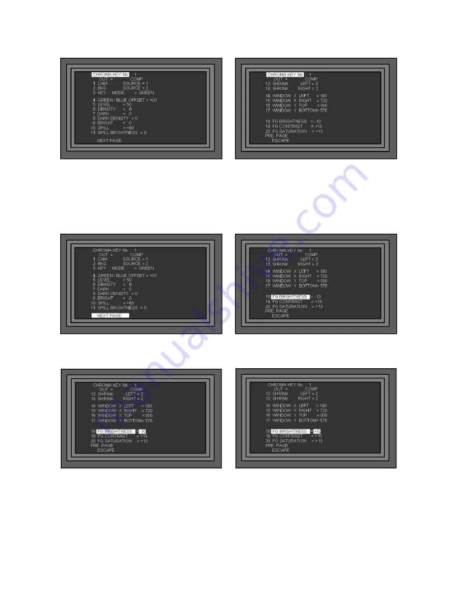
This example is one of the more complex menus “Chroma Key”. You can see that it is two pages long. The 
principles used here apply to all of the System Set Up Menus. 


To open the Chroma Key Menu, press the Setting Key to call up the System Menu Display,  
highlight 1. CHROMA KEY and press the Enter Key. The first page of the Chroma Key Menu will be 
displayed. 
 
To change the value of line 18. FG BRIGHTNESS, you need to get to the second page of the menu. To do 
this navigate to the bottom line of the first page “NEXT PAGE” and press the Enter Key. Then use the Adjust 
Knob, or Down Key to navigate down to 18. FG BRIGHTNESS so that it becomes highlighted. 


With 18. FG BRIGHTNESS highlighted press the Enter Key, you will see the value, in this case -10, 
becomes highlighted. Use the Adjust Knob, or Up / Down Keys to adjust the value, in this case to +02 


Once the value is set you can either, press the Enter Key, then navigate down to the next setting that you 
require, or to ESCAPE, and press the Enter Key again, or simply press the ESC Key three times to leave the 
System Set Up and return to normal operation. 
 

Summary of Contents for SE-900

Page 1: ...SE 900 Digital Video Switcher Instruction Manual www datavideo tek com Rev 150109...

Page 2: ...ol Panel 13 LCD Display 14 I O Card Options 15 Fitting an I O Card 18 Setting Up 20 Power Connections 20 Monitor Connections 21 Video Connections 23 Audio Connections 25 Powering On 28 Set Up Menus 29...

Page 3: ...tness 41 Modifying the Labels 41 Control Panel 42 Overview 42 Adjustments and Setup 43 Main Source and Sub Source Rails 44 T Bar and Take Keys 46 Effects and Transitions 47 Joystick 49 Preset Effects...

Page 4: ...the Background 68 CK SYNC Operation 69 Luma Keying 70 Setting up a Luma Key 71 Logo Display 72 Overview 72 Setting up a Logo 72 Luma Keying with Logo Function 73 DSK Down Stream Keying CG Graphic Ove...

Page 5: ...5 Reset 82 PAL NTSC 83 Updating Firmware 84 Checking Firmware Revisions 86 Specification 87 Optional Datavideo Accessory Items for the SE 900 88 Service and Support 89...

Page 6: ...at the total of the ampere ratings on the products plugged into the extension cord do not exceed the extension cord s rating 10 Make sure that the total amperes of all the units that are plugged into...

Page 7: ...n the product indicates that it will not be treated as household waste It must be handed over to the applicable take back scheme for the recycling of electrical and electronic equipment For more detai...

Page 8: ...CH simultaneously video outputs of SDI x 2 DV YUV Composite and S Y C Multi image monitoring Preview Output Multi image monitoring output for 8 CH video inputs source Press on PREVIEW key to preview t...

Page 9: ...o The Base Station is also modular you can fit up to 8 input cards of your choice You can also choose different output options and additional feature cards such as Chroma Key and External Sync Base Un...

Page 10: ...unit has a ventilation panel to prevent overheating please ensure that adequate airflow is provided The main power On Off switch is in the upper left corner of the Base Unit front panel If power is co...

Page 11: ...S Video Y C Component Video YUV and DV Outputs Slot 15 Remote Control This card provides RS 232C RS 422 and GPI connections for remotely controlling the SE 900 The card also features an SD Card which...

Page 12: ...fourth Slot 11 Multi Image Preview Out Multi Image Preview minimises the number of monitors required for a set up All input channels the next source and the output channel are all displayed on one sc...

Page 13: ...e to use a longer cable if required The control panel is supplied with a power supply with the standard 1 2m cable between the Control Panel and the Base Unit it is not necessary to use the power supp...

Page 14: ...has been selected and the colour and size of the border BDR The selected background colour BG The Cued Source PST The Live Source PGM The LCD Display will also show the System Set Up Menus which are u...

Page 15: ...audio output via mini XLR Cables It also provides a composite video monitor output Slots 1 8 SDI Input The SDI Input card takes SD SDI with embedded audio The card will de embed the SDI Audio and pro...

Page 16: ...DV output also carries embedded audio from the Audio Delay Circuit Supplied as standard Slot 13 SDI Output The SDI output card provides two SD SDI video outputs with embedded audio from the Audio Dela...

Page 17: ...ying to create Each of the four channels are independent so you could have two green keys a blue key on the third channel and Luma Key on the fourth Slot 15 Remote Control This card provides RS 232C R...

Page 18: ...t the top and bottom of each plate and it will pull away The slots are numbered from 1 to 15 certain slots are for certain cards 1 8 Are for input cards Analogue SDI DV DVI 9 Is for the Chroma Key Car...

Page 19: ...ristband or ensure that you are properly grounded by any other means ESD damage to cards is rare but will not be covered by warranty if it occurs so be careful To fit a card ensure that you are ground...

Page 20: ...a 12v 1200mA power supply is supplied If you are using a short connection between the Base Unit and the Control Panel it is not necessary to use it With Sub D 9 Pin cables of up to 10m it should not b...

Page 21: ...GM It will also supply basic tally information by highlighting the live source with a red border and the cued source with a yellow border The Multi Image Preview output is supplied via YUV Y Pb Pr Com...

Page 22: ...outputs it is possible to connect ten monitors one for each input plus one for PST and one for PGM to the SE 900 This is an example configuration Illustrated are two Datavideo TLM 404 4 x 4 Monitors a...

Page 23: ...nt video inputs This unlikely illustration shows examples of the different input types that could be connected The analogue inputs can be set to CV Composite Y C S Video YUV Component in the Video Inp...

Page 24: ...Component YUV Y Pb Pr Composite and S Video The SDI and DV outputs can both have embedded audio The SDI Card also has a Black Burst Output to provide synchronisation to other devices This example doe...

Page 25: ...audio connections which provide balanced audio for you to feed to an external audio mixer The Audio Delay Circuit allows you to add a delay to the audio stream in order to maintain lip sync on your re...

Page 26: ...2 frames DV DV 3 frames SDI DV 2 frames DVI DV N A CV Analogue Video 1 frame S Video Analogue Video 1 frame YUV Analogue Video 1 frame DV Analogue Video 2 frames SDI Analogue Video 1 frame DVI Analogu...

Page 27: ...could take audio out from each of your DV and SDI Video Inputs feed them all to an audio mixer and then take the balanced audio mixer feed and put it through the Audio Delay Circuit The output from th...

Page 28: ...Pin cables of up to 10m it should not be necessary to use the additional power supply for the control panel as power can be drawn from the Base Unit with longer cables the loss may be too great If the...

Page 29: ...in the LCD Display of the Control Panel The Menus are navigated using the Adjust Knob and the Adjust Keys The Set Up Menu is opened by pressing the Setting Key and looks like this N B The Control Pan...

Page 30: ...nu To do this navigate to the bottom line of the first page NEXT PAGE and press the Enter Key Then use the Adjust Knob or Down Key to navigate down to 18 FG BRIGHTNESS so that it becomes highlighted W...

Page 31: ...lid at 64 the subject becomes softer and partially transparent 7 DARK 0 64 Adjusts the shadow detail of the subject 0 is no shadow and 64 gives a harder shadow 8 DARK DENSITY 0 64 Adjusts the density...

Page 32: ...ble to get the lighting of the shot as close as possible to perfect before fine tuning 18 FG BRIGHTNESS 99 99 Adjusts the brightness of the foreground subject Default is 00 19 FG CONTRAST 99 99 Adjust...

Page 33: ...vel to 0 or 7 5 This is only necessary for NTSC SDI OUT 1 BLACK_BURST CV BLACK_BURST CV Sets the Black Burst CV Output on the SDI Board to either BLACK_BURST or Composite Video 4 LOGO LUMA KEY Title V...

Page 34: ...4 TRANSPARENCY 0 100 Sets the transparency level of the overlay 0 is opaque 100 is very transparent Applies to INTERNAL Mode only 5 VER OFFSET OF SDI_IN 0 32 Used to correct the alignment of the SDI o...

Page 35: ...he display name of Input 3 9 CAM4_NAME CAM4 Up to 7 Characters Allows you to customise the display name of Input 4 A CAM5_NAME CAM5 Up to 7 Characters Allows you to customise the display name of Input...

Page 36: ...o factory defaults 12 UPDATE FIRMWARE Title Values Description 1 NORMAL RECOMMENDED Switches the Audio Delay Circuit On Off 2 DETAIL Sets the delay time in either frames or milli seconds according to...

Page 37: ...hlight to update the Preview Output Board software 12 CG BOARD Highlight to update the CG Overlay Board software 13 SDI OUT Highlight to update the SDI Output Board software 14 AV DV OUT Highlight to...

Page 38: ...D 9 Pin cables of up to 10m it should not be necessary to use the additional power supply for the control panel as power can be drawn from the Base Unit with longer cables the loss may be too great I...

Page 39: ...output to 90 or 80 The Active Live Input is bordered in Red and the Cued Input is bordered in Yellow In the example above CAM1 is Active you will see that it is in the PGM window and CAM3 is Cued you...

Page 40: ...verall output press the Setting Key to call up the Set Up Menus highlight option 7 MULTI IMAGE and press the Enter Key It is advisable to have the Multi Image Preview on the Screen so that you can see...

Page 41: ...quirements For example you may want to use the names of the crew or label a channel B Roll or DVD Each description can be up to seven characters long To modify the Label for CAM1 press the Setting Key...

Page 42: ...this You will notice that the CK SYNC and CK Keys on the Main and Sub Source Rails do not light up during normal operation this is intentional The LCD display should be in Status Display Mode and if...

Page 43: ...d Set Up All of the settings for the SE 900 are controlled from the LCD Display and the Adjustment Keys Knob The LCD display will display the status of the SE 900 during operation and will display the...

Page 44: ...the rail The Sub Source Rail shows the Cued channel this channel will appear in the PST preview window N B The keys on the Main and Sub Source Rails will be inactive while the T Bar is active Only wh...

Page 45: ...ming lines The Status Display will indicate the active background The background can be changed using the BG Colour Key CK Stands for Chroma Key If you are using the Chroma Key function these will bec...

Page 46: ...inactive while the T Bar is active Only when the T Bar is fully up or fully down will the keys respond The GPI TAKE Key will perform automatic takes based on the 10 Preset Effects The first press of t...

Page 47: ...around the screen using the Joystick Position Control See Mosaic in the Effects section for more details Paint effect can be applied in one of six different preset levels See Paint in the Effects sec...

Page 48: ...ing Lines The active BG Colour is indicated in the Status Display Transitions The SE 900 features 14 programmable wipe patterns and an A B dissolve All wipes can have optional colour borders applied a...

Page 49: ...Green Blue sets the Joystick to colour correction mode for Video Input setting POS CNTL Position Control sets the Joystick to positioning mode for PIP and Mosaic effects Preset Effects You can program...

Page 50: ...hts up as active and then press F1 for F6 F2 for F7 and so on For more information about programming the presets please see Storing and Recalling Presets Level Speed The Level Speed keys set the speed...

Page 51: ...TNESS and press the Enter Key Use the Adjustment Knob to change the setting and then press the ESC Key to exit 3 REMOTE MODE RS 232 is the only remote mode at present 4 SWITCH COLOR This changes the d...

Page 52: ...ve a red border and the plane a yellow border to indicate they are the Live and Cued sources The Main Source Rail shows Channel 3 is Live and the Sub Source Rail shows Channel 2 is Cued Multi Image Pr...

Page 53: ...the speed you can either repeatedly press the SPD Key or directly select the speed you want using the numbered speed level keys The active speed will be indicated in Status Display and also by the num...

Page 54: ...which can be applied to the video image PIP Picture in Picture Picture in Picture displays the sub source image in a small window which is superimposed over the main source This window can be set to o...

Page 55: ...ng the following Keys TOP LEFT BOTTOM RIGHT BOTTOM LEFT TOP RIGHT It is also possible to position the PIP in any other area by using the Joystick Position Control With PIP active press the POS CNTL Ke...

Page 56: ...he BDR Key The Status Display will show the following options BORDER No Border BORDER N Color Narrow Border BORDER M Color Medium Border BORDER W Color Wide Border You can set the Border Colour by rep...

Page 57: ...e same channel this is so that the Mosaic Effect can be seen previewed over the Live output Once set up the Mosaic Effect can be sent live to obscure part of the screen You could also set the effect u...

Page 58: ...el Speed Keys are being used to control the Level The Speed will be indicated in the Status Display Strobe Press the STRB Key to activate the Strobe Effect You will see that a number of Keys do not li...

Page 59: ...e being used to control the Level The Speed will be indicated in the Status Display Colour Correction Colour correction is applied to each video input channel individually The settings are stored per...

Page 60: ...upon the position of the Joystick The X Axis is horizontal movement and the Y Axis is vertical movement 00 00 is the central position With the RGB Values highlighted press the RGB Key to activate the...

Page 61: ...to call up the Set Up Menu highlight 2 VIDEO IN and press the Enter Key Highlight VIDEO_IN CH and press the Enter Key the Channel number will be highlighted Use the Adjustment Knob to select the Chan...

Page 62: ...oma Key Sync Standard chroma keying allows up to four channels to be set up for chroma keying while the rest of the channels can be used conventionally The chroma key source can be keyed over any of t...

Page 63: ...set up in advance of going live Press the CK Key so that it becomes active and then press the Take Key so that the CK Key on the Main Source Rail also becomes active It doesn t matter at this stage w...

Page 64: ...ob to scroll down the menu to 1 CAM SOURCE Using the same procedure as above ENTER ADJUST ESCAPE set the CAM SOURCE Foreground and then scroll down to 2 BKG SOURCE and set the BKG SOURCE Background In...

Page 65: ...e to get a semi transparent background go to 5 LEVEL and increase the value to 10 then try again Keep increasing the LEVEL 5 LEVEL Level increases decreases the colour range that is keyed If your ligh...

Page 66: ...he left of the subject Use just enough to give a clean edge 13 SHRINK RIGHT Shrink Right can remove any unwanted edge from the right of the subject Use just enough to give a clean edge Window adjustme...

Page 67: ...to use for keying On the Sub Source Rail press the channel number that you want to use as the source for keying In this example we want to use Channel 1 If everything is set up correctly the key shou...

Page 68: ...Channel 7 in this example You will see the background change in the PST window Once you have selected the background that you want press the CK key on the Sub Source Rail so that it changes from yello...

Page 69: ...We also have four virtual sets on CAM5 CAM6 CAM7 and CAM8 When you are setting up each of the chroma channels it is important to make sure that your foreground source 1 CAM SOURCE and your background...

Page 70: ...CAM2 CAM3 and CAM4 by pressing the keys 1 2 3 4 on the Main Rail As switch you will see the backgrounds switch with the foregrounds so the parings are maintained It is only possible to switch between...

Page 71: ...he setup options for Luma Key are different to those of Chroma Key 4 DARK LEVEL Sets the level of black that is removed as you increase the value you will see increasingly lighter shades of grey are r...

Page 72: ...to butt together and form one large logo You can use two completely separate logos each 128 x 96 pixels or if you want a larger logo split the image into two The logos are positioned on the screen usi...

Page 73: ...and the new logo will be shown in place of the old logo Luma Keying with Logo Function With the SE 900 you can Luma Key in two ways either with the Logo function or with the Chroma Key function You ne...

Page 74: ...rlay to be added to the finished output External DSK relies on an external card such as a Blackmagic Design Card to overlay the graphics and return the signal to the SE 900 With Internal DSK the SE 90...

Page 75: ...75 Internal DSK External DSK...

Page 76: ...ound from the CG Input Set 4 TRANSPARENCY to give the overlay a semi transparent appearance 5 VER OFFSET of SDI_IN adjusts the position of the overlay on the screen Press the ESC Key three times to ex...

Page 77: ...all up the AUDIO DELAY Setting Menu 1 AUDIO _ DELAY Sets the Audio Delay circuit On Off 2 DELAY _ TIME Sets the Delay Time in either frames or units of 10mS according to the setting of 3 TIME_UNIT 3 T...

Page 78: ...ght option 11 STORE RECALL Press the Enter Key to call up the STORE RECALL Menu Highlight 1 STORE FUNC KEY and press the Enter Key then use the Adjustment Knob to select the Preset that you want to st...

Page 79: ...d to offer powered tally light information The TB 5 connects directly to the Tally Output Port and then supplies bi colour tally information with 12V DC power via 4 x 3 5mm Jack Sockets You would need...

Page 80: ...Jack Socket which is situated on the Remote Control Card Contact closure between the Outer and Inner contacts will trigger the next effect RS 232 The SE 900 features an RS 232 port which is situated...

Page 81: ...want it press the Settings Key to call up the Set Up Menus and highlight option 11 STORE RECALL Press the Enter Key to call up the STORE RECALL Menu Highlight STORE TO USER_1 and press the Enter Key t...

Page 82: ...ing for store message has gone you gone press the ESC Key three times to leave the Set Up Menus and resume normal operation The SE 900 settings will have changed to the recalled values RESET To return...

Page 83: ...ff and remove the Remote Control Board from slot 15 of the Base Unit You will see a small jumper at the front of the board which can be simply removed and re positioned The jumper position for NTSC or...

Page 84: ...mputer The firmware must be loaded to the root directory of the SD Card i e not in a folder Re insert the SD Card and re fit the Remote Control Card to the SE 900 base unit Power the SE 900 up and wai...

Page 85: ...ystem Highlight the option that you want to update by scrolling down the menu with the Adjustment Knob Once the option is highlighted press the RESET Key for 2 seconds until the Update Script starts t...

Page 86: ...FIRMWARE Press the Enter Key to call up the Update Menu Highlight 3 READ VERSION and press the Enter Key this will call up page 1 of the Software Version Sub Menu You can see the firmware versions fo...

Page 87: ...c Bandwidth 20 20KHz 2dB Distortion 0 1 S N 65 dB Audio Delay Delay control from 1 Frames to 16 Frames Chroma Key 4 2 2 Dual graphic Processor Chroma key Module Optional item Video Effects FTB Wipes Z...

Page 88: ...nt TLM 170M SDI Desktop TLM 170MD 1U SDI 19 rack mount 4 models available depending on your requirement See Monitor Connections on page 21 of this manual TLM 702 19 Rack mountable 1 unit with 2 x 7 LC...

Page 89: ...eo nl www datavideo info Datavideo UK Limited Unit 2 Waterside Business Park Hadfield Glossop Derbyshire SK13 1BE UK Tel 44 1457 851000 sales datavideo co uk www datavideo info Datavideo Technologies...

Reviews: