


DV9500
30
3
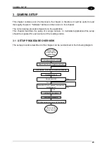
3.2 CAMERA PARAMETERS SETUP
The first step after the mechanical and electrical mounting is the camera parameter setup.
You can easily view and edit all camera parameters using Genius™ (see par. 4.1)
Camera parameters depend heavily on the application.
Paragraph 4.2 gives an overview of these parameters.
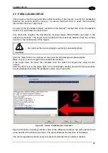
3.3 SPEED, POSITION AND TRIGGER SENSOR CHECK
The camera usually requires some speed, position and trigger sensors to be connected and
properly set-up.
The first time you switch the camera on and every time you have problems with these
sensors you can easily check them using Genius™ “Test” tool (see par. 5.2).
If the OE digital input is used as a speed sensor the “Digital I/O” page of the “Test” tool can
be used to check if there is any activity on this input. The ‘LED’ on this page should reflect
exactly the status of the physical OE LED on the camera back panel.
Whichever speed sensor is used you can read the current speed on the “Sensors.Speed
sensor” page of the test tool.
Please notice that the “Digital I/O” page shows the status of the physical input, while the
“Sensors.Speed sensor” page shows the status of the logical sensor.
In case of activity on the physical input and bad speed measurement check the speed sensor
parameter setting.
If the PS digital input is used as a trigger source the “Digital I/O” page of the “Test” tool can
be used to check the status of this input. The ‘LED’ on this page should reflect exactly the
status of the physical PS LED on the camera back panel.
Whichever trigger source is used you can read the current trigger status on the
“Sensors.Speed sensor” or “Sensors.Position sensor” pages of the test tool.
In case of activity on the physical input and no trigger detected check the trigger source
parameter setting.
You can also check the current height or side position using the “Sensors.Position sensor”
page of the test tool.
Summary of Contents for DV9500 Series
Page 1: ...DV9500 Installation Manual ...
Page 2: ......