


DV9500
22
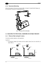
2
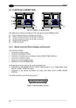
2.6 ELECTRICAL CONNECTIONS
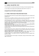
Figure 18 – DV9500 – Connectors panels
The following connectors are present on the rear panels of the DV9500 camera:
A)
Main connector (25 pin D-sub Male connector)
B)
COM1 connector (9 pin D-sub Female connector)
C)
COM2 connector (9 pin D-sub Female connector)
D) Camera-Link
connectors
E) LVDS
connectors
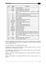
2.6.1 Main Connector (Power Supply and Sensors)
This connector allows:
•
connection to power supply
•
connection to presence sensor
•
connection to height sensor or distance sensor (COM3, RS422 interface)
•
connection to optical encoder
•
driving of an external digital output
•
sensing of an external digital signal
With appropriate factory setting, the connector allows also:
•
connection to the decoder PC for runtime communication or for configuration using
Genius™ (COM1, RS232 interface)
•
connection to the system illuminators for power and status control (COM2, RS232
interface).
The Main Connector has the following pinout:
14
1
25
13
Figure 19 - Main 25-pin Male Connector
E
D
A
C
B
Summary of Contents for DV9500 Series
Page 1: ...DV9500 Installation Manual ...
Page 2: ......


