INSTALLATION
17
2
Should the barriers be used as a trigger source in a multisided station the rule must
be applied to all cameras, not only the TOP one.
•
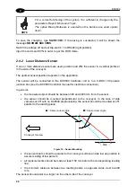
The sensed area should be exactly perpendicular to the conveyor.
The barriers will be connected to the DC9500 Controller unit or to a C-BOX 100 passive
junction box. (see the DC9500 Controller manual for electrical connection).
If the standard LCC-9006/LCC-9010 light curtains are used:
1) Position and affix the barriers onto the vertical profiles ahead of the scan line (considering
the conveyor direction). Use the 4 screws and nuts on the edges of each bar. The
barriers maximum reading distance is: 4900 mm.
2) Verify the bar alignment and check that they are at the same distance from the belt
surface.
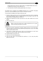
3) Open the control unit.
WARNING
When you open the control unit, to prevent electrical shock, the power
cable must be disconnected from the mains.
4) Mount one of the two compression connectors contained in the kit in front of the power
connector (bottom left corner near the transformer) and the other in front of the “Serial
COM” connector (top left corner).
5) Verify that the 110-220V power selector switch near the transformer is in the correct
position and connect the power cable to the power screw connector.
6) Connect the bars to the control unit.
7) Close the control unit and apply power.
8) Verify the green LED on the transmitter bar switches on. If not, verify the perfect
alignment of the bars.
Summary of Contents for DV9500 Series
Page 1: ...DV9500 Installation Manual ...
Page 2: ......


