SOFTWARE
47
4
4.2.3 Equalization
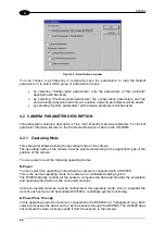
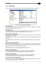
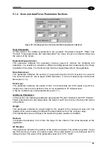
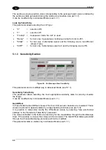
This folder groups the configuration parameters used to define the camera equalization.
Figure 41 – Parameters Explorer: Equalization
Pixel Equalization
This parameter enables the Inter-pixel Equalization table. For more details refer to the Inter-
pixel Equalization procedure in par. 4.2.3.
Light Equalization
This parameter enables the Light Profile Equalization for both Look-up table 0 and 1. For
more details refer to the Light Profile Equalization procedure in par. 5.5.
Digital Gain#1, Digital Gain#2
This parameter is a multiplication factor of the gray level of each pixel of this image; it must
be set between 1.0 and 4.0.
The default value is 1.0 but it can be increased when the light level is insufficient for correct
decoding.
Digital Gain#1 acts on Look-up table 0 (LUT0) while Digital Gain#2 acts on Look-up table 1
(LUT1).
Digital Offset#1, Digital Offset#2
These values are added to the gray level of each acquired pixel. The possible values are
from -100 to 100. The default value is 0 but it can be increased (to reduce the image
contrast) or decreased (to increase the image contrast).
Digital Offset#1 acts on LUT0 while Digital Offset#2 acts on LUT1.
Dynamic Offset Equalization
This parameter enables the runtime channel offset monitoring and optimization.
For more details refer to the Parameter Reference Table in the CD-ROM.
Dynamic Gain Equalization
This parameter enables the runtime channel gain monitoring and optimization.
For more details refer to the Parameter Reference Table in the CD-ROM.
Look-Up Table Threshold Height (mm)
LUT0 is used to acquire images at high distances (short packages) while LUT1 is used to
acquire images at low distances (high packages).
Summary of Contents for DV9500 Series
Page 1: ...DV9500 Installation Manual ...
Page 2: ......

