4.
5.
1.
2.
-
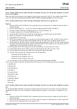
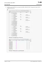
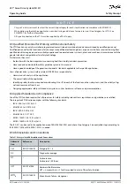
Map the inputs and outputs of the instance of the
AXIS_REF_DDS
function block and the physical data points of the ISD 511
servo drive (here
myAxis
is an instance of
AXIS_REF_DDS
):
e30bg343.10
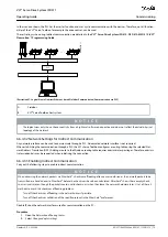
Illustration 45: I/O Mapping of an ISD 511 Servo Drive
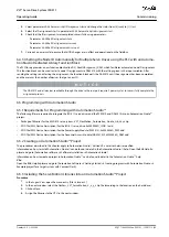
Map the inputs and outputs of the instance of the
PSM_REF
,
DAM_REF
, and
ACM_REF
function blocks and the physical data
points of the PSM 510/DAM 510/ACM 510 accordingly.
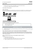
6.5.12 Setting the PLC Cycle Time
The minimum cycle time is 400 µs. The servo system devices can run Ethernet POWERLINK
®
cycle times in multiples of 400 µs and
multiples of 500 µs. The devices are automatically parameterized by the PLC on start-up, depending on the Ethernet POWERLINK
®
configuration of the physical interface.
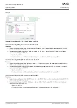
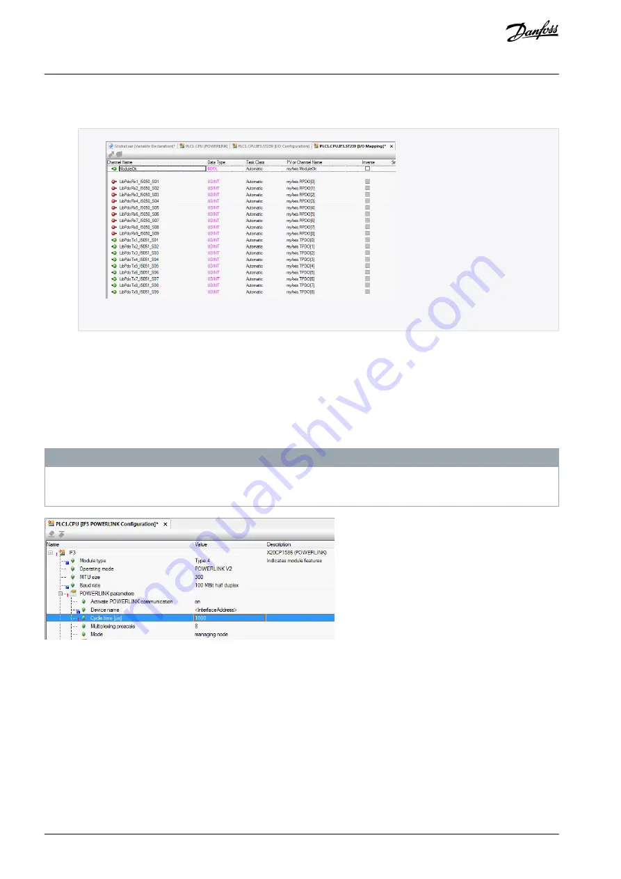
The Ethernet POWERLINK
®
configuration can be accessed by right-clicking [PLK
→
Configuration] in the
Physical View
.
N O T I C E
Ensure that the task cycle times of the PLC program and Ethernet POWERLINK
®
are the same. Otherwise, data could be lost
and performance reduced.
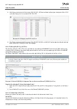
e30bg344.10
Illustration 46: Ethernet POWERLINK<
®
Configuration Window to Parameterize Ethernet POWERLINK
®
Cycle Time
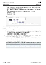
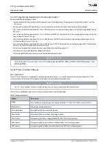
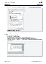
Procedure for setting the PLC time in Automation Studio
™
Right-click [CPU
→
Open Software Configuration] for V3.0.90 and [CPU
→
Configuration
→
Timing] for V4.x in the
Physical
View
.
Ensure that the PLC cycle time is the same as the Ethernet POWERLINK
®
cycle time.
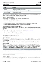
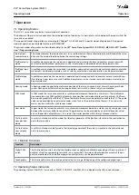
6.5.13 Connecting to the PLC
Information on how to connect to the PLC can be found in detail in the Automation Studio
™
Help.
Version V4.x:
Open the
B&R Help Explorer
and go to [Automation Software
→
Getting Started
→
Creating programs in Automation Studio
→
Ex-
ample project for a target system with CompactFlash].
AQ377148425069en-000101
/ 130R1213
76 | Danfoss A/S © 2023.08
Commissioning
VLT® Servo Drive System ISD 511
Operating Guide


