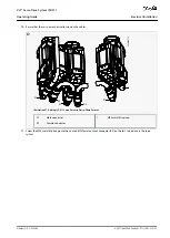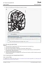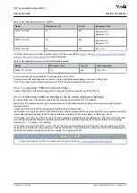
1.
2.
3.
4.
5.
6.
7.
8.
9.
10.
5.9.2.2 Connecting the Cables on the Power Supply Module PSM 510
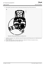
5.9.2.2.1 Connecting the Cables on the Top of the Power Supply Module PSM 510
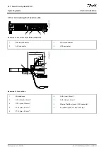
1
2
3
4
5
6
7
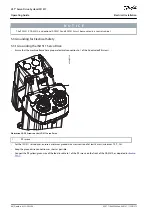
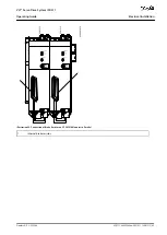
e30bg465.11
Illustration 29: Connectors on the Top of PSM 510
1
Ethernet connector IN (X1 IN)
2
Ethernet connector OUT (X2 OUT)
3
24/48 V IN connector (INPUT 24/48 V)
4
STO connector IN (STO PSM)
5
STO connector OUT (STO PSM)
6
I/O connector (I/O PSM)
7
Relay connector (REL PSM)
Procedure
Connect the Ethernet cable from the PLC to the Ethernet input connector (X1 IN) [1].
Connect the Ethernet cable from the Ethernet output connector (X2 OUT) [2] to the next module.
Insert the wires into the 24/48 V IN (INPUT 24/48 V) connector.
Insert the 24/48 V IN connector [3].
Insert the wires into the STO connector IN (STO PSM) connector.
Insert the STO connector IN connector [4].
Insert the wires into the STO connector OUT (STO PSM) connector.
Insert the STO connector OUT connector [5].
If I/Os are required, insert the wires into the I/O connector and insert the connector (I/O PSM) [6].
If a relay is required, insert the wires into the relay connector and insert the connector (REL PSM) [7].
AQ377148425069en-000101
/ 130R1213
58 | Danfoss A/S © 2023.08
Electrical Installation
VLT® Servo Drive System ISD 511
Operating Guide

