12.
1.
2.
3.
4.
5.
6.
-
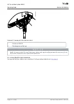
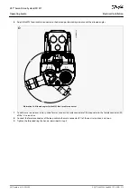
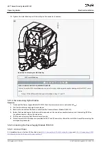
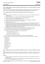
Tighten the metal blind cap until the sealing on the connector is covered.
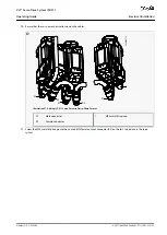
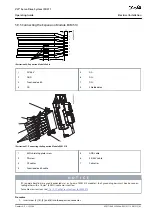
1
e30bk206.10
Illustration 28: Mounting the M23 Blind Cap
1
M23 metal blind cap
C A U T I O N
RISK OF INJURY AND/OR EQUIPMENT DAMAGE
Failure to use the M23 metal blind cap may result in injury to the operator and/or damage to the ISD 511 servo
drive.
Always fit the M23 metal blind cap as described in steps 11 and 12.
5.9.1.4 Disconnecting Hybrid Cables
Procedure
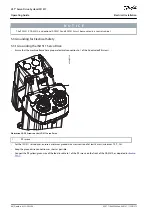
Disconnect the Power Supply Module (PSM 510) from its power source (mains network and U
AUX
).
Wait for the minimum discharge time to elapse.
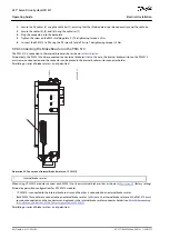
Remove the connector of the feed-in cable from the Decentral Access Module (DAM 510).
Rotate the threaded ring on the feed-in cable connector on the servo drive counterclockwise until the marking OPEN on
the cable connector is facing the servo drive.
Pull the connector away from the electronic housing.
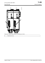
Protective metal M23 blind caps are provided for the X1 and X2 connectors. Mount the metal blind caps after removing the
corresponding connector.
5.9.2 Connecting the Power Supply Module PSM 510
5.9.2.1 AC Line Choke
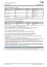
It is mandatory to use a 3-phase AC line choke (see
5.9.2.1.1 Connecting 1 PSM 510 to the AC Choke
510 Modules to the AC Choke with System Splitting
).
AQ377148425069en-000101
/ 130R1213
56 | Danfoss A/S © 2023.08
Electrical Installation
VLT® Servo Drive System ISD 511
Operating Guide


