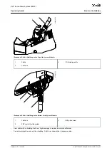
1.
-
-
-
-
-
-
-
-
5.8 UL Requirements
N O T I C E
Integral solid-state short-circuit protection does not provide branch circuit protection. Branch circuit protection must be pro-
vided in accordance with the National Electrical Code/Canadian Electrical Code, and any additional local codes or equivalent.
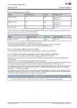
Suitable for use on a circuit capable of delivering not more than 5000 rms symmetrical amperes, 480 V maximum when pro-
tected by maximum 80 A class J or T fuses.
To meet the UL (Underwriters Laboratories) regulations, use a UL-approved copper cable with a minimum heat-resistance of
60 °C. Use Class 1 wire only. For PSM 510 rated 30 kW and EXM 510, use a minimum heat resistance of 75 °C.
Control Circuit Overcurrent Protection is required.
5.9 Connecting the Components
5.9.1 Connecting the ISD 511 Servo Drive
5.9.1.1 Electrical Installation Warnings for ISD 511 Servo Drive
W A R N I N G
HIGH VOLTAGE
Potentially lethal voltage is present on the connectors that may lead to death or serious injury.
Before working on the power or signal connectors (disconnecting or connecting the cable), or performing any maintenance
work, disconnect the Power Supply Module (PSM 510) from the mains and wait for the discharge time to elapse.
W A R N I N G
DISCHARGE TIME
The servo system contains DC-link capacitors that remain charged for some time after the mains supply is switched off at the
Power Supply Module (PSM 510). Failure to wait the specified time after power has been removed before performing service or
repair work could result in death or serious injury.
To avoid electrical shock, fully disconnect the Power Supply Module (PSM 510) from the mains and wait for the capacitors to
fully discharge before carrying out any maintenance work on the servo system or replacing components.
Minimum waiting time (minutes)
15
5.9.1.2 General Instructions for Cable Installation
Avoid mechanical tension for all cables, especially regarding the range of motion of the installed servo drive.
Secure all cables in accordance with regulations and depending on conditions on site. Ensure that cables cannot come loose, even
after prolonged operation.
N O T I C E
Never connect or disconnect the hybrid cables to or from the servo drive when the supply voltage is present. Doing so dam-
ages the electronic circuitry. Observe the discharge time for the DC-link capacitors.
Do not forcefully connect or fit the connectors. Incorrect connection causes permanent damage to the connector.
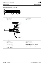
5.9.1.3 Connecting Hybrid Cables
Procedure
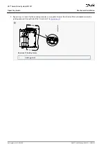
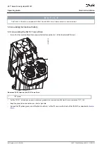
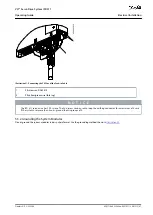
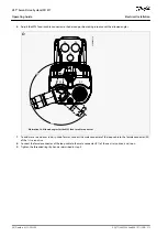
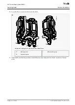
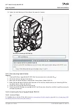
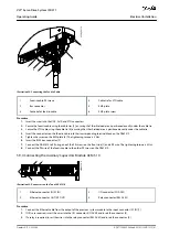
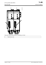
Align the female connector of the M23 feed-in cable to the male input connector (X1) of the 1st ISD 511 servo drive.
AQ377148425069en-000101
/ 130R1213
52 | Danfoss A/S © 2023.08
Electrical Installation
VLT® Servo Drive System ISD 511
Operating Guide


