


colored differently to distinguish CAN and power supply from cables with analog control signals. When
using AMP the gray connector is dedicated for CAN and electric power supply and the black for
connecting analogue devices to the PVED. Deutsch connectors are not-keyed, but PVED-CL is laser-
marked with description.
AMP connectors
CR
CL
P
T
T
LVDT
Neutral spring
T
P (12bar+T)
Contour of
PVG 32 casting
AMP-connector
(Gray)
AMP-connector
(Black)
2
D
A
5V
t
u
o 1D
A
D
N
G
A
C
N
H_
a
b-
V
t
A
C
N
L_
D
N
G
P005 092E
Electronic Controller Unit
The 4-pin AMP (Junior Power Timer) has been designed especially for the
automotive industries where high reliability and safety is required.
The features of the AMP connectors are:
Separate insulation of each lead ensures minimum risk of short cutting
•
•
Safe JPT locking
•
•
Safe locking of housing
•
•
Mechanical coding of housing
•
•
IP 66
•
•
•
•
which prevents mistakes during installation
Easy disassembly
•
•
Electronic Control Unit
The Electronic Control Unit (ECU) performs the following tasks:
•
CAN messages. The PVED hardware is compatible to CAN 2.0B
•
Converting two analogue input voltages between 0 and 5V to digital signals (10 bit)
•
Executing the steering software & monitoring for discrepancies with fixed time intervals
•
Output the main spool position setpoint
•
Controlling the LED color
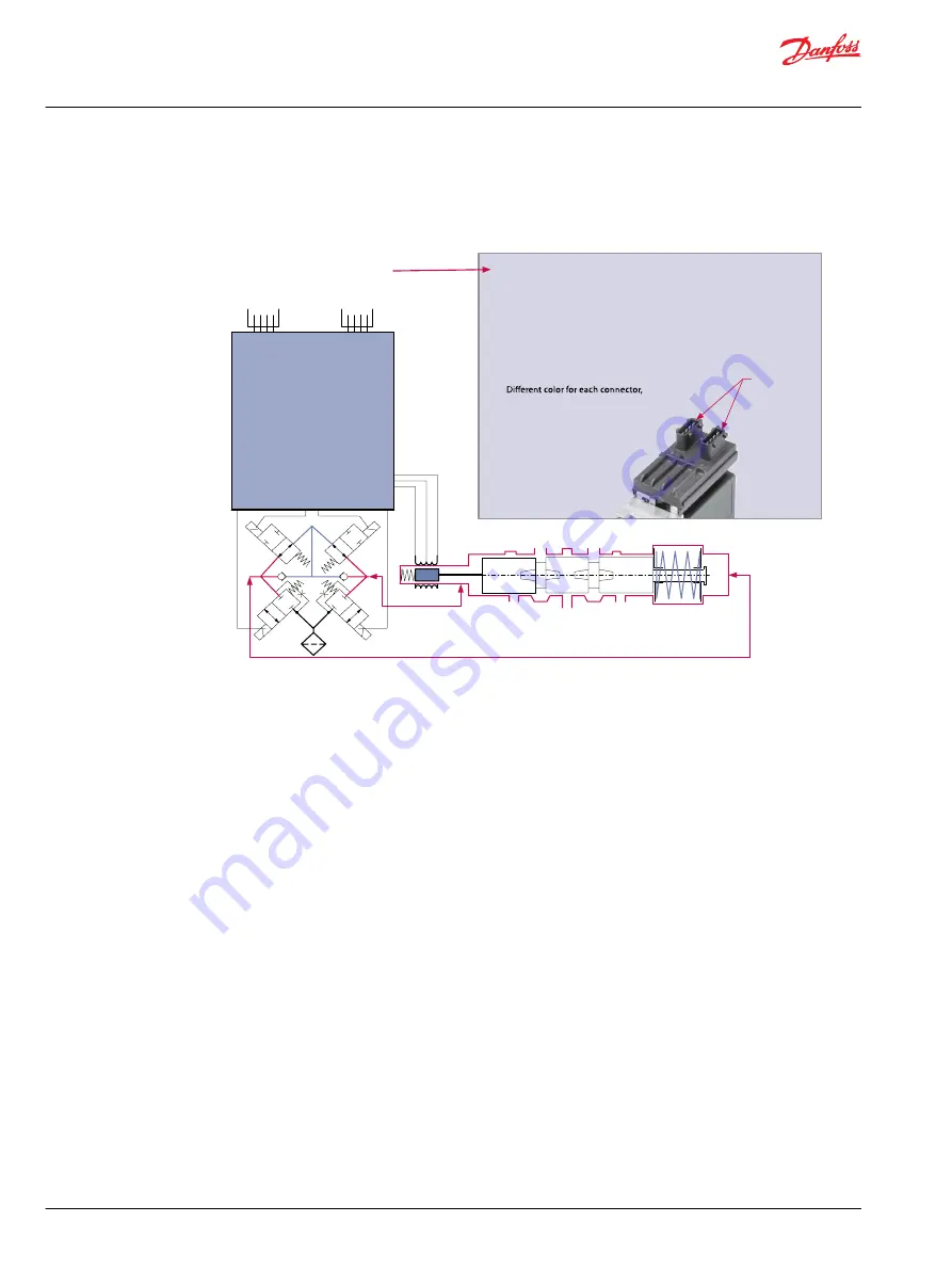
Solenoid Valve Bridge
The PVED-CL features an integrated feedback transducer that measures spool movement in relation to
the input signal from the main micro controller, and by means of a solenoid valve bridge, controls the
direction, velocity, and position of the main spool of the valve. The integrated electronics compensate for
flow forces on the spool, internal leakage, changes in oil viscosity, pilot pressure, etc. This results in lower
hysteresis and better resolution.
Control Principle
In principle the input signal (set-point signal) determines the level of pilot pressure, which moves the
main spool. The position of the main spool is sensed in the LVDT transducer, which generates an electric
feedback signal registered by the electronics. The variation between the set-point signal and feedback
signal activates the solenoid valves. The solenoid valves are actuated so that hydraulic pressure drives the
main spool into the correct position.
Operation Manual
PVED-CL Controller for Electro-Hydraulic Steering, Version 1.38
Configuration and Adjustment
20 |
©
Danfoss | May 2016
11025583 | AQ00000216en-US0302