


MiniMax
Bolt Tension Monitor
185
2) The
and
arrow keys to scroll through the sub menu items until
DEFAULT SETUP
is highlighted.
3) Press the
key to load default
DEFAULT SETUP
.
4) Finally, press the
key to return to the measurement screen.
15.6 Selecting a Language
The
MiniMax
is equipped with a language option. Currently, only a few languages
supported. However, be sure to update your gauge firmware often, to check for
language additions. The steps to select a language are outlined as follows:
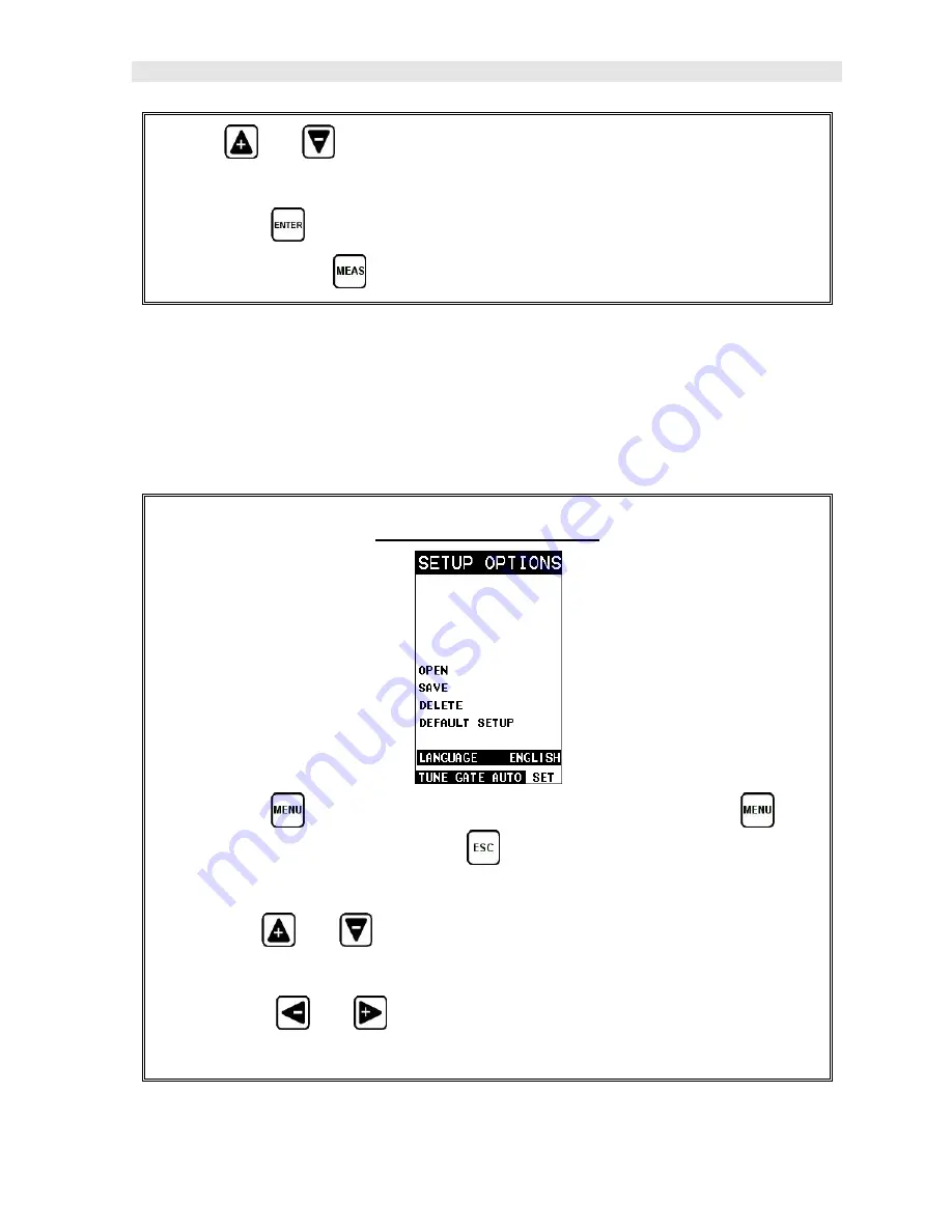
Selecting a Language
1) Press the
key once to activate the menu items tab. Press the
key
multiple times to tab right and the
key multiple times to tab left until the
SETUP
menu is highlighted and displaying the submenu items.
2) Use the
and
arrow keys to scroll through the sub menu items until
LANGUAGE
is highlighted.
3) Press the
and
arrow keys multiple times to toggle the language
options.
Summary of Contents for MiniMax v2.0
Page 2: ......
Page 49: ...MiniMax Bolt Tension Monitor 43 Figure 6 Reflection in a bending bolt...
Page 196: ......


