


Special Control
Si39-502A
60
Function
3.
Special Control
3.1
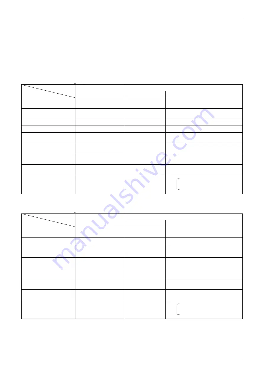
Startup Control
This control is used to equalize the pressure in the front and back of the compressor prior to the startup of the
compressor, thus reducing startup loads. Furthermore, the inverter is turned ON to charge the capacitor.
In addition, to avoid stresses to the compressor due to oil return or else after the startup, the following control is made
and the position of the four way valve is also determined.
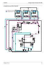
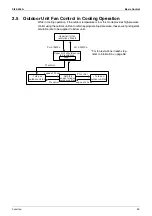
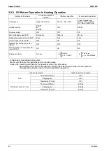
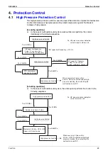
3.1.1 Startup Control in Cooling Operation
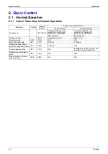
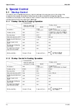
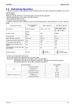
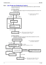
3.1.2 Startup Control in Heating Operation
Thermostat ON
Pressure equalization
control prior to startup
Startup control
STEP1
STEP2
Compressor
OFF
52Hz
+OFF +OFF
+2 steps/20 sec.
(until Pc - Pe>0.39MPa is achieved)
Outdoor unit fan
OFF
OFF
+1 step/15 sec. (when Pc>2.16MPa)
-1 step/15 sec. (when Pc<1.77MPa)
Four way valve
OFF
OFF
OFF
Main motorized valve (EV1)
0 pls
2000 pls
2000 pls
Subcooling motorized valve
(EV2)
0 pls
0 pls
0 pls
Hot gas bypass valve
(SVP)
OFF
ON
ON
Receiver gas discharging
valve (SVG)
OFF
OFF
OFF
Non-operating unit liquid
pipe stop valve (SVSL)
ON
ON
ON
Ending conditions
A lapse of 15 sec.
A lapse of 5 sec.
•
A lapse of 320 sec.
•
Pc - Pe>0.39MPa
OR
Thermostat ON
Pressure equalization
control prior to startup
Startup control
STEP1
STEP2
Compressor
OFF
52Hz
+OFF +OFF
+2 steps/20 sec.
(until Pc - Pe>0.39MPa is achieved)
Outdoor unit fan
STEP4
OFF
STEP8
Four way valve
ON
ON
ON
Main motorized valve (EV1)
0 pls
0 pls
0 pls or 180 pls
Subcooling motorized valve
(EV2)
0 pls
0 pls
0 pls
Hot gas bypass valve
(SVP)
OFF
ON
ON
Receiver gas discharging
valve (SVG)
OFF
OFF
OFF
Non-operating unit liquid
pipe stop valve (SVSL)
ON
ON
ON
Ending conditions
A lapse of 15 sec.
A lapse of 5 sec.
•
A lapse of 130 sec.
•
Pc>2.94MPa
OR
Summary of Contents for VRV II RXYQ8MY1K
Page 53: ...Specifications Si39 502A 42 Specifications...
Page 143: ...Field Setting Si39 502A 132 Test Operation...
Page 258: ...Si39 502A Wiring Diagrams for Reference Appendix 247 FXCQ40M 50M 80M 125MVE 3D039557A...
Page 260: ...Si39 502A Wiring Diagrams for Reference Appendix 249 FXKQ25M 32M 40M 63MVE 3D039564A...
Page 264: ...Si39 502A Wiring Diagrams for Reference Appendix 253 FXMQ40M 50M 63M 80M 100M 125MVE 3D039620A...
Page 265: ...Wiring Diagrams for Reference Si39 502A 254 Appendix FXMQ200M 250MVE 3D039621A...
Page 266: ...Si39 502A Wiring Diagrams for Reference Appendix 255 FXHQ32M 63M 100MVE 3D039801C...
Page 267: ...Wiring Diagrams for Reference Si39 502A 256 Appendix FXAQ20M 25M 32M 40M 50M 63MVE 3D034206A...
Page 269: ...Wiring Diagrams for Reference Si39 502A 258 Appendix FXUQ71M 100M 125MV1 3D044973...
Page 270: ...Si39 502A Wiring Diagrams for Reference Appendix 259 FXAQ20MH 25MH 32MH 40MH 50MHV1 3D046348A...
Page 271: ...Wiring Diagrams for Reference Si39 502A 260 Appendix FXLQ20MH 25MH 32MH 40MH 50MHV1 3D046787A...
Page 272: ...Si39 502A Wiring Diagrams for Reference Appendix 261 BEVQ50MVE 3D046579A Notes...
Page 273: ...Wiring Diagrams for Reference Si39 502A 262 Appendix BEVQ71M 100M 125MVE 3D044901A Notes...
Page 285: ...Piping Installation Point Si39 502A 274 Appendix...
Page 293: ...Method of Replacing The Inverter s Power Transistors and Diode Modules Si39 502A 282 Appendix...
Page 307: ...Si39 502A iv Index...


