


Si39-502A
Field Setting
Test Operation
115
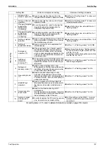
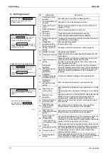
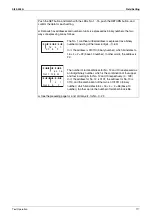
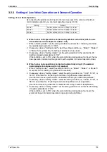
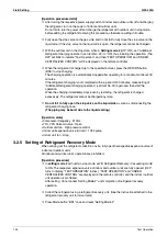
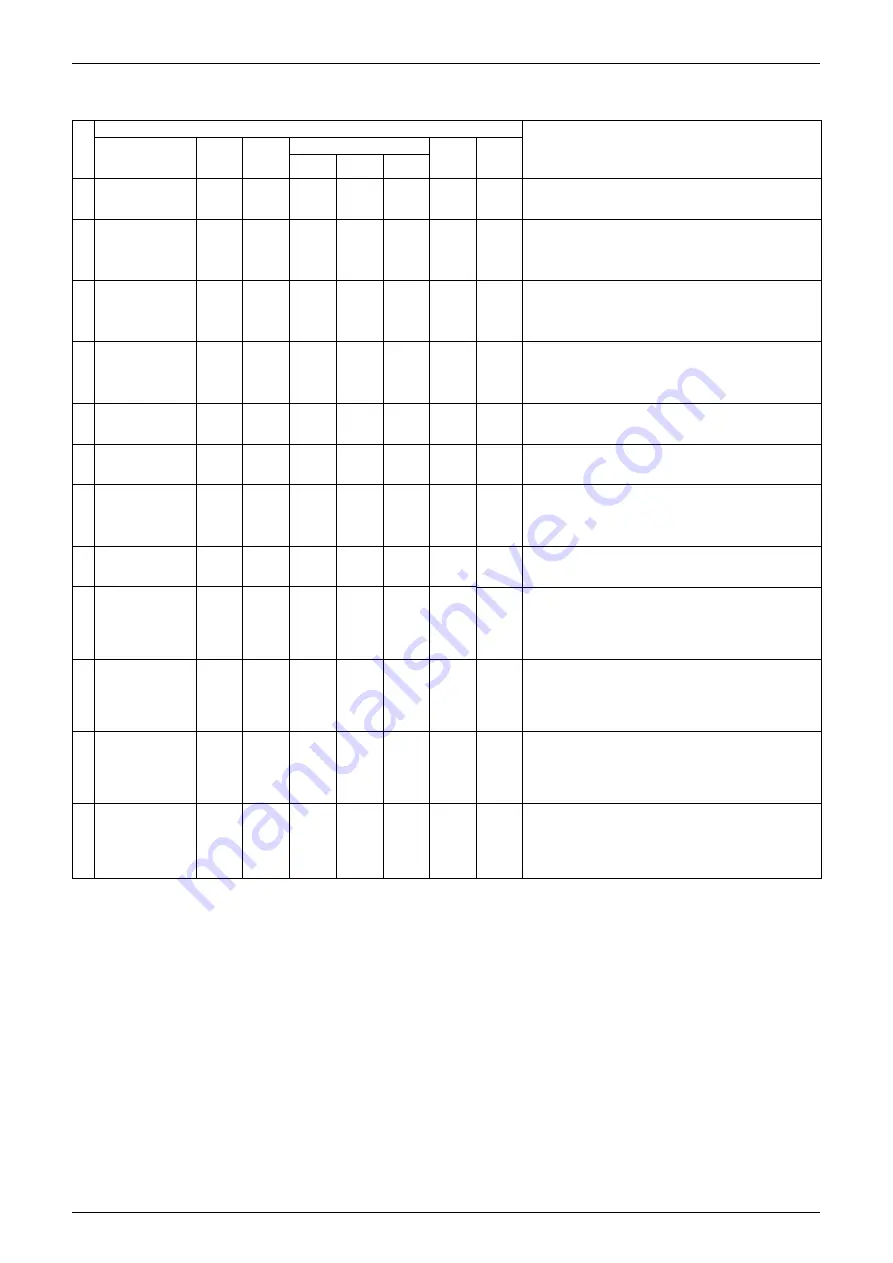
No.
Setting item display
Setting condition display
Setting item
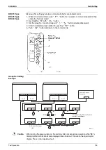
MODE
H1P
TEST
H2P
C/H selection
Low
noise
H6P
Demand
H7P
IND
H3P
Master
H4P
Slave
H5P
∗
Factory set
24
ENECUT test
operation (Domestic
Japan only)
8
7
8
8
7
7
7
EneCut output OFF
8777778
∗
EneCut output forced ON
8777787
25 Low noise setting
8
7
8
8
7
7
8
Level 1 (outdoor fan with 8 step or lower)
8777778
Level 2 (outdoor fan with 7 step or lower)
8777787
∗
Level 3 (outdoor fan with 6 step or lower)
8777877
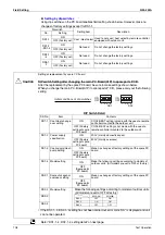
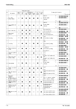
26
Night-time low noise
operation start
setting
8
7
8
8
7
8
7
About 20:00
8777778
About 22:00 (factory setting)
8777787
∗
About 24:00
8777877
27
Night-time low noise
operation end setting
8
7
8
8
7
8
8
About 6:00
8777778
About 7:00
8777787
About 8:00 (factory setting)
8777877
∗
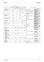
28
Power transistor
check mode
8
7
8
8
8
7
7
OFF
8777778
∗
ON
8777787
29
Capacity
precedence setting
8
7
8
8
8
7
8
OFF
8777778
∗
ON
8777787
30 Demand setting 1
8
7
8
8
8
8
7
60 % demand
8777778
70 % demand
8777787
∗
80 % demand
8777877
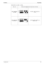
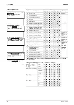
32
Normal demand
setting
8
8
7
7
7
7
7
OFF
8777778
∗
ON
8777787
38
Emergency
operation
(Master unit with
multi-outdoor-unit
system is inhibited to
operate.)
8
8
7
7
8
8
7
OFF
8777778
∗
Master unit operation: Inhibited
8777787
39
Emergency
operation
(Slave unit 1 with
multi-outdoor-unit
system is inhibited to
operate.)
8
8
7
7
8
8
8
OFF
8777778
∗
Slave unit 1 operation: Inhibited
8777787
40
Emergency
operation
(Slave unit 2 with
multi-outdoor-unit
system is inhibited to
operate.)
8
8
7
8
7
7
7
OFF
8777778
∗
Slave unit 2 operation: Inhibited
8777787
42
Emergency
operation
(prohibition of INV
compressor
operation)
8
8
7
8
7
8
7
Normal operation
8777778
∗
Emergency operation
(prohibition of INV compressor
operation)
8777787
Summary of Contents for VRV II RXYQ8MY1K
Page 53: ...Specifications Si39 502A 42 Specifications...
Page 143: ...Field Setting Si39 502A 132 Test Operation...
Page 258: ...Si39 502A Wiring Diagrams for Reference Appendix 247 FXCQ40M 50M 80M 125MVE 3D039557A...
Page 260: ...Si39 502A Wiring Diagrams for Reference Appendix 249 FXKQ25M 32M 40M 63MVE 3D039564A...
Page 264: ...Si39 502A Wiring Diagrams for Reference Appendix 253 FXMQ40M 50M 63M 80M 100M 125MVE 3D039620A...
Page 265: ...Wiring Diagrams for Reference Si39 502A 254 Appendix FXMQ200M 250MVE 3D039621A...
Page 266: ...Si39 502A Wiring Diagrams for Reference Appendix 255 FXHQ32M 63M 100MVE 3D039801C...
Page 267: ...Wiring Diagrams for Reference Si39 502A 256 Appendix FXAQ20M 25M 32M 40M 50M 63MVE 3D034206A...
Page 269: ...Wiring Diagrams for Reference Si39 502A 258 Appendix FXUQ71M 100M 125MV1 3D044973...
Page 270: ...Si39 502A Wiring Diagrams for Reference Appendix 259 FXAQ20MH 25MH 32MH 40MH 50MHV1 3D046348A...
Page 271: ...Wiring Diagrams for Reference Si39 502A 260 Appendix FXLQ20MH 25MH 32MH 40MH 50MHV1 3D046787A...
Page 272: ...Si39 502A Wiring Diagrams for Reference Appendix 261 BEVQ50MVE 3D046579A Notes...
Page 273: ...Wiring Diagrams for Reference Si39 502A 262 Appendix BEVQ71M 100M 125MVE 3D044901A Notes...
Page 285: ...Piping Installation Point Si39 502A 274 Appendix...
Page 293: ...Method of Replacing The Inverter s Power Transistors and Diode Modules Si39 502A 282 Appendix...
Page 307: ...Si39 502A iv Index...


