


Si39-502A
Troubleshooting by Indication on the Remote Controller
Troubleshooting
155
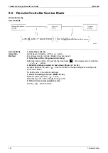
3.4
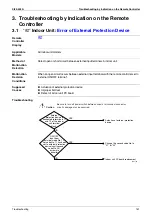
“
A6
”
Indoor Unit:
Fan Motor (M1F) Lock, Overload
Remote
Controller
Display
A6
Applicable
Models
All indoor units
Method of
Malfunction
Detection
Detection by failure of signal for detecting number of turns to come from the fan motor
Malfunction
Decision
Conditions
When number of turns can’t be detected even when output voltage to the fan is maximum
Supposed
Causes
Fan motor lock
Disconnected or faulty wiring between fan motor and PC board
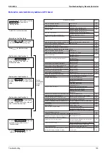
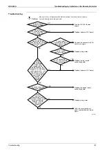
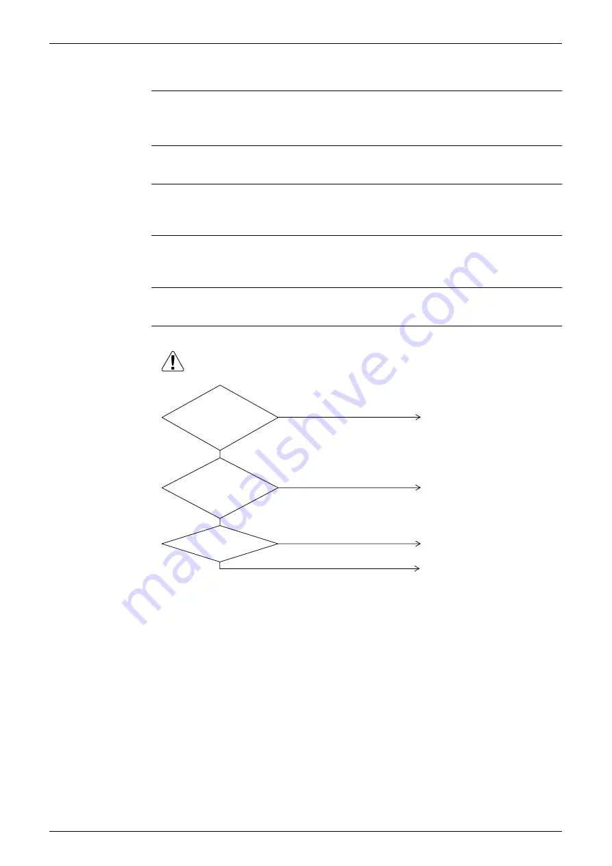
Troubleshooting
Caution
Be sure to turn off power switch before connect or disconnect connector,
or parts damage may be occurred.
Connect the wiring and turn on
again.
Fix the wiring and turn on again.
YES
NO
NO
NO
YES
YES
Replace the indoor unit PC board.
Replace the fan motor.
Is the
wiring from the fan
motor securely connected
to connectors on the
indoor unit PC
board?
Wiring
between the
indoor unit PC board and
fan motor is
disconnected.
Does the fan motor run?
(V2779)
Summary of Contents for VRV II RXYQ8MY1K
Page 53: ...Specifications Si39 502A 42 Specifications...
Page 143: ...Field Setting Si39 502A 132 Test Operation...
Page 258: ...Si39 502A Wiring Diagrams for Reference Appendix 247 FXCQ40M 50M 80M 125MVE 3D039557A...
Page 260: ...Si39 502A Wiring Diagrams for Reference Appendix 249 FXKQ25M 32M 40M 63MVE 3D039564A...
Page 264: ...Si39 502A Wiring Diagrams for Reference Appendix 253 FXMQ40M 50M 63M 80M 100M 125MVE 3D039620A...
Page 265: ...Wiring Diagrams for Reference Si39 502A 254 Appendix FXMQ200M 250MVE 3D039621A...
Page 266: ...Si39 502A Wiring Diagrams for Reference Appendix 255 FXHQ32M 63M 100MVE 3D039801C...
Page 267: ...Wiring Diagrams for Reference Si39 502A 256 Appendix FXAQ20M 25M 32M 40M 50M 63MVE 3D034206A...
Page 269: ...Wiring Diagrams for Reference Si39 502A 258 Appendix FXUQ71M 100M 125MV1 3D044973...
Page 270: ...Si39 502A Wiring Diagrams for Reference Appendix 259 FXAQ20MH 25MH 32MH 40MH 50MHV1 3D046348A...
Page 271: ...Wiring Diagrams for Reference Si39 502A 260 Appendix FXLQ20MH 25MH 32MH 40MH 50MHV1 3D046787A...
Page 272: ...Si39 502A Wiring Diagrams for Reference Appendix 261 BEVQ50MVE 3D046579A Notes...
Page 273: ...Wiring Diagrams for Reference Si39 502A 262 Appendix BEVQ71M 100M 125MVE 3D044901A Notes...
Page 285: ...Piping Installation Point Si39 502A 274 Appendix...
Page 293: ...Method of Replacing The Inverter s Power Transistors and Diode Modules Si39 502A 282 Appendix...
Page 307: ...Si39 502A iv Index...


