


Symptom-based Troubleshooting
Si39-502A
138
Troubleshooting
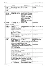
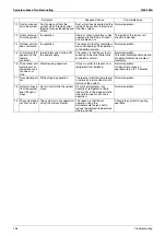
Symptom
Supposed Cause
Countermeasure
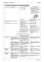
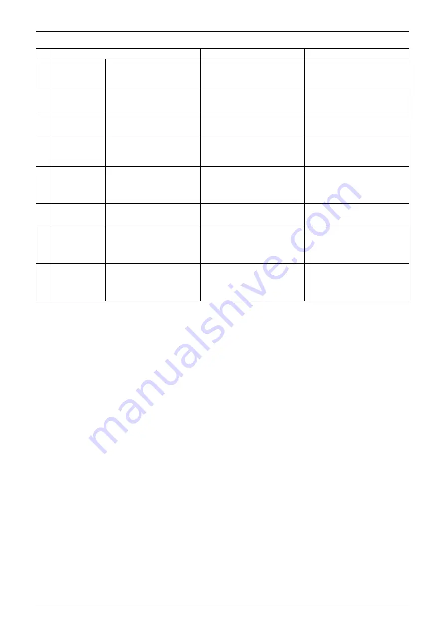
12 Dust comes out
from the system.
Dust comes out from the
system when it restarts after
the stop for an extended period
of time.
Dust, which has deposited on the
inside of indoor unit, is blown out
from the system.
Normal operation.
13 Odors come out
from the system.
In operation
Odors of room, cigarettes or else
adsorbed to the inside of indoor
unit are blown out.
The inside of the indoor unit
should be cleaned.
14 Outdoor unit fan
does not rotate.
In operation
The reason is that fan revolutions
are controlled to put the operation
to the optimum state.
Normal operation.
15 LCD display "88"
appears on the
remote
controller.
Immediately after turning ON
the power supply
The reason is that the system is
checking to be sure the remote
controller is normal.
Normal operation.
This code is displayed for a period
of approximately one minute at
maximum.
16 The outdoor unit
compressor or
the outdoor unit
fan does not
stop.
After stopping operation
It stops in order to prevent oil or
refrigerant from dwelling.
Normal operation.
It stops after a lapse of
approximately 5 to 10 minutes.
17 The outdoor gets
hot.
While stopping operation
The reason is that the compressor
is warmed up to provide smooth
startup of the system.
Normal operation.
18 Hot air comes in
from the system
even though it
stops.
Hot air is felt while the system
stops.
On multi-unit systems, tiny
quantity of refrigerant is fed to
indoor units in the stopped state
when other indoor units are in
operation.
Normal operation.
19 The system does
not cool air well.
The system is in dry operation
using the microcomputer.
The reason is that the dry
operation using the
microcomputer serves not to
reduce the ambient temperature
where possible.
Change the system to cooling
operation.
Summary of Contents for VRV II RXYQ8MY1K
Page 53: ...Specifications Si39 502A 42 Specifications...
Page 143: ...Field Setting Si39 502A 132 Test Operation...
Page 258: ...Si39 502A Wiring Diagrams for Reference Appendix 247 FXCQ40M 50M 80M 125MVE 3D039557A...
Page 260: ...Si39 502A Wiring Diagrams for Reference Appendix 249 FXKQ25M 32M 40M 63MVE 3D039564A...
Page 264: ...Si39 502A Wiring Diagrams for Reference Appendix 253 FXMQ40M 50M 63M 80M 100M 125MVE 3D039620A...
Page 265: ...Wiring Diagrams for Reference Si39 502A 254 Appendix FXMQ200M 250MVE 3D039621A...
Page 266: ...Si39 502A Wiring Diagrams for Reference Appendix 255 FXHQ32M 63M 100MVE 3D039801C...
Page 267: ...Wiring Diagrams for Reference Si39 502A 256 Appendix FXAQ20M 25M 32M 40M 50M 63MVE 3D034206A...
Page 269: ...Wiring Diagrams for Reference Si39 502A 258 Appendix FXUQ71M 100M 125MV1 3D044973...
Page 270: ...Si39 502A Wiring Diagrams for Reference Appendix 259 FXAQ20MH 25MH 32MH 40MH 50MHV1 3D046348A...
Page 271: ...Wiring Diagrams for Reference Si39 502A 260 Appendix FXLQ20MH 25MH 32MH 40MH 50MHV1 3D046787A...
Page 272: ...Si39 502A Wiring Diagrams for Reference Appendix 261 BEVQ50MVE 3D046579A Notes...
Page 273: ...Wiring Diagrams for Reference Si39 502A 262 Appendix BEVQ71M 100M 125MVE 3D044901A Notes...
Page 285: ...Piping Installation Point Si39 502A 274 Appendix...
Page 293: ...Method of Replacing The Inverter s Power Transistors and Diode Modules Si39 502A 282 Appendix...
Page 307: ...Si39 502A iv Index...


