


Si39-502A
Troubleshooting by Remote Controller
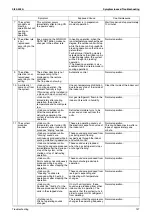
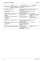
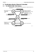
Troubleshooting
145
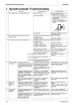
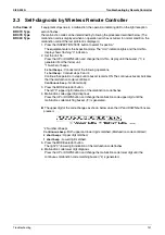
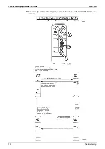
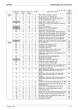
Mode
No
Function
Contents and operation method
Remote controller display example
40
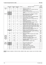
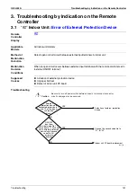
Malfunction
hysteresis display
Display malfunction hysteresis.
The history No. can be changed with the
button.
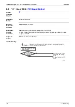
41
Display of sensor
and address data
Display various types of data.
Select the data to be displayed with the
button. Sensor data
0: Thermostat sensor in remote controller.
1: Suction
2: Liquid pipe
3: Gas pipe
Address data
4: Indoor unit address
5: Outdoor unit address
6: BS unit address
7: Zone control address
8: Cool/heat group address
9: Demand / low noise address
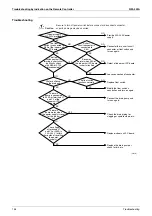
43
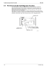
Forced fan ON
Manually turn the fan ON by each unit. (When
you want to search for the unit No.)
By selecting the unit No. with the
button,
you can turn the fan of each indoor unit on
(forced ON) individually.
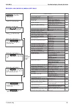
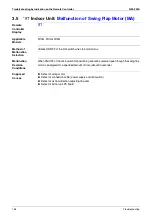
44
Individual setting
Set the fan speed and air flow direction by each
unit
Select the unit No. with the time mode
button. Set the fan speed with the
button.
Set the air flow direction with the
button.
45
Unit No. transfer
Transfer unit No.
Select the unit No. with the
button.
Set the unit No. after transfer with the
button.
46
This function is not used by VRV ll R-410A Heat Pump 50/60Hz.
47
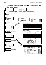
Hystory No: 1 - 9
1: Latest
Unit 1
Malfunction code
2-U4
Malfunction code
40
(VE007)
Temperature ºC
41
Sensor data display
Unit No.
Sensor type
1 1
2 7
Address
41
Address display
Unit No.
Address type
1 8
1
(VE008)
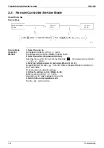
Unit 1
43
(VE009)
Unit 1
Code
44
Air flow direction
P0 - P4
Fan speed 1: Low
3: High
1 3
(VE010)
Unit 1
Code
45
Present unit No.
Unit No. after
transfer
0 2
(VE011)
Summary of Contents for VRV II RXYQ8MY1K
Page 53: ...Specifications Si39 502A 42 Specifications...
Page 143: ...Field Setting Si39 502A 132 Test Operation...
Page 258: ...Si39 502A Wiring Diagrams for Reference Appendix 247 FXCQ40M 50M 80M 125MVE 3D039557A...
Page 260: ...Si39 502A Wiring Diagrams for Reference Appendix 249 FXKQ25M 32M 40M 63MVE 3D039564A...
Page 264: ...Si39 502A Wiring Diagrams for Reference Appendix 253 FXMQ40M 50M 63M 80M 100M 125MVE 3D039620A...
Page 265: ...Wiring Diagrams for Reference Si39 502A 254 Appendix FXMQ200M 250MVE 3D039621A...
Page 266: ...Si39 502A Wiring Diagrams for Reference Appendix 255 FXHQ32M 63M 100MVE 3D039801C...
Page 267: ...Wiring Diagrams for Reference Si39 502A 256 Appendix FXAQ20M 25M 32M 40M 50M 63MVE 3D034206A...
Page 269: ...Wiring Diagrams for Reference Si39 502A 258 Appendix FXUQ71M 100M 125MV1 3D044973...
Page 270: ...Si39 502A Wiring Diagrams for Reference Appendix 259 FXAQ20MH 25MH 32MH 40MH 50MHV1 3D046348A...
Page 271: ...Wiring Diagrams for Reference Si39 502A 260 Appendix FXLQ20MH 25MH 32MH 40MH 50MHV1 3D046787A...
Page 272: ...Si39 502A Wiring Diagrams for Reference Appendix 261 BEVQ50MVE 3D046579A Notes...
Page 273: ...Wiring Diagrams for Reference Si39 502A 262 Appendix BEVQ71M 100M 125MVE 3D044901A Notes...
Page 285: ...Piping Installation Point Si39 502A 274 Appendix...
Page 293: ...Method of Replacing The Inverter s Power Transistors and Diode Modules Si39 502A 282 Appendix...
Page 307: ...Si39 502A iv Index...


