


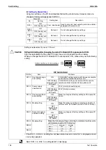
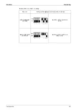


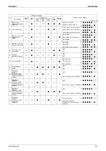


Field Setting
Si39-502A
104
Test Operation
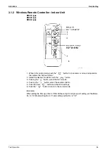
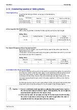
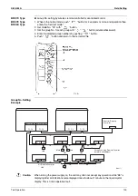
3.1.8 Setting of Operation Control Mode from Remote Controller
(Local Setting)
The operation control mode is compatible with a variety of controls and operations by limiting
the functions of the operation remote controller. Furthermore, operations such as remote
controller ON/OFF can be limited in accordance with the combination conditions. (Refer to
information in the table below.)
Central remote controller is normally available for operations. (Except when centralized monitor
is connected)
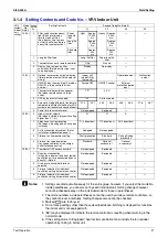
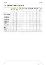
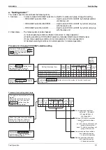
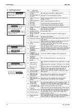
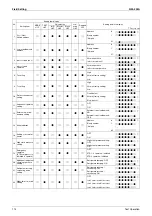
3.1.9 Contents of Control Modes
Twenty modes consisting of combinations of the following five operation modes with
temperature and operation mode setting by remote controller can be set and displayed by
operation modes 0 through 19.
ON/OFF control impossible by remote controller
Used when you want to turn on/off by central remote controller only.
(Cannot be turned on/off by remote controller.)
OFF control only possible by remote controller
Used when you want to turn on by central remote controller only, and off by remote controller
only.
Centralized
Used when you want to turn on by central remote controller only, and turn on/off freely by
remote controller during set time.
Individual
Used when you want to turn on/off by both central remote controller and remote controller.
Timer operation possible by remote controller
Used when you want to turn on/off by remote controller during set time and you do not want
to start operation by central remote controller when time of system start is programmed.
Summary of Contents for VRV II RXYQ8MY1K
Page 53: ...Specifications Si39 502A 42 Specifications...
Page 143: ...Field Setting Si39 502A 132 Test Operation...
Page 258: ...Si39 502A Wiring Diagrams for Reference Appendix 247 FXCQ40M 50M 80M 125MVE 3D039557A...
Page 260: ...Si39 502A Wiring Diagrams for Reference Appendix 249 FXKQ25M 32M 40M 63MVE 3D039564A...
Page 264: ...Si39 502A Wiring Diagrams for Reference Appendix 253 FXMQ40M 50M 63M 80M 100M 125MVE 3D039620A...
Page 265: ...Wiring Diagrams for Reference Si39 502A 254 Appendix FXMQ200M 250MVE 3D039621A...
Page 266: ...Si39 502A Wiring Diagrams for Reference Appendix 255 FXHQ32M 63M 100MVE 3D039801C...
Page 267: ...Wiring Diagrams for Reference Si39 502A 256 Appendix FXAQ20M 25M 32M 40M 50M 63MVE 3D034206A...
Page 269: ...Wiring Diagrams for Reference Si39 502A 258 Appendix FXUQ71M 100M 125MV1 3D044973...
Page 270: ...Si39 502A Wiring Diagrams for Reference Appendix 259 FXAQ20MH 25MH 32MH 40MH 50MHV1 3D046348A...
Page 271: ...Wiring Diagrams for Reference Si39 502A 260 Appendix FXLQ20MH 25MH 32MH 40MH 50MHV1 3D046787A...
Page 272: ...Si39 502A Wiring Diagrams for Reference Appendix 261 BEVQ50MVE 3D046579A Notes...
Page 273: ...Wiring Diagrams for Reference Si39 502A 262 Appendix BEVQ71M 100M 125MVE 3D044901A Notes...
Page 285: ...Piping Installation Point Si39 502A 274 Appendix...
Page 293: ...Method of Replacing The Inverter s Power Transistors and Diode Modules Si39 502A 282 Appendix...
Page 307: ...Si39 502A iv Index...


