


Si39-502A
Troubleshooting (OP: Unified ON/OFF Controller)
Troubleshooting
229
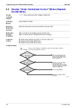
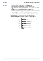
6.2
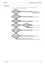
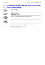
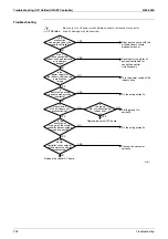
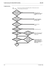
Display “Under Centralized Control” Blinks (Repeats
Single Blink)
Remote
Controller
Display
“under centralized control” (Repeats single blink)
Applicable
Models
Unified ON/OFF controller
Central remote controller, Schedule timer
Method of
Malfunction
Detection
Detect the malfunction according to DIII-NET transmission data.
Malfunction
Decision
Conditions
When the centralized controller, which was connected once, shows no response.
The control ranges are overlapped.
When multiple master central controller are present.
When the schedule timer is set to individual use mode, other central controller is present.
When the wiring adaptor for electrical appendices is present.
Supposed
Causes
Address duplication of optional controllers for centralized control
Improper combination of optional controllers for centralized control
Connection of more than one master controller
Malfunction of transmission between optional controllers for centralized control
Defect of PC board of optional controllers for centralized control
Summary of Contents for VRV II RXYQ8MY1K
Page 53: ...Specifications Si39 502A 42 Specifications...
Page 143: ...Field Setting Si39 502A 132 Test Operation...
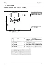
Page 258: ...Si39 502A Wiring Diagrams for Reference Appendix 247 FXCQ40M 50M 80M 125MVE 3D039557A...
Page 260: ...Si39 502A Wiring Diagrams for Reference Appendix 249 FXKQ25M 32M 40M 63MVE 3D039564A...
Page 264: ...Si39 502A Wiring Diagrams for Reference Appendix 253 FXMQ40M 50M 63M 80M 100M 125MVE 3D039620A...
Page 265: ...Wiring Diagrams for Reference Si39 502A 254 Appendix FXMQ200M 250MVE 3D039621A...
Page 266: ...Si39 502A Wiring Diagrams for Reference Appendix 255 FXHQ32M 63M 100MVE 3D039801C...
Page 267: ...Wiring Diagrams for Reference Si39 502A 256 Appendix FXAQ20M 25M 32M 40M 50M 63MVE 3D034206A...
Page 269: ...Wiring Diagrams for Reference Si39 502A 258 Appendix FXUQ71M 100M 125MV1 3D044973...
Page 270: ...Si39 502A Wiring Diagrams for Reference Appendix 259 FXAQ20MH 25MH 32MH 40MH 50MHV1 3D046348A...
Page 271: ...Wiring Diagrams for Reference Si39 502A 260 Appendix FXLQ20MH 25MH 32MH 40MH 50MHV1 3D046787A...
Page 272: ...Si39 502A Wiring Diagrams for Reference Appendix 261 BEVQ50MVE 3D046579A Notes...
Page 273: ...Wiring Diagrams for Reference Si39 502A 262 Appendix BEVQ71M 100M 125MVE 3D044901A Notes...
Page 285: ...Piping Installation Point Si39 502A 274 Appendix...
Page 293: ...Method of Replacing The Inverter s Power Transistors and Diode Modules Si39 502A 282 Appendix...
Page 307: ...Si39 502A iv Index...


