Field Setting
Si39-502A
130
Test Operation
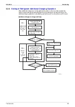
[Operation procedure detail]
c
After turning the respective power supply switch of indoor and outdoor units off and charging
the refrigerant, turn on the power of indoor and outdoor units.
Do not fail to turn the power off and charge the refrigerant with outdoor unit in stop mode
before adding the refrigerant following this procedure, otherwise resulting in trouble.
d
Fully open the stop valve on the gas side, and do not fail to fully close the stop valve on the
liquid side. (If the stop valve on the liquid side is open, the refrigerant cannot be charged.)
e
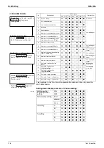
With the outdoor unit in the stop state, while in
Setting mode 2
(H1P: ON), set “Additional
Refrigerant charging operation” (set item No. 20) to "ON", thus initiating the operation. (The
H2P will blink to indicate "Test Operation", and then "TEST OPERATION" and "UNDER
CENTRALIZED CONTROL" will be displayed on the remote controller.
f
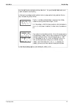
When the refrigerant is charged up to the specified amount, press the RETURN button
(BS3) to stop charging.
The charging operation is automatically stopped after operating for a maximum of about 30
minutes.
If the refrigerant charging is not completed within a period of 30 minutes, make setting of
“Additional Refrigerant charging operation” (set item No. 20) again and then start the
operation.
When the charging immediately stops even by restarting, the refrigerant is charged
excessively. The refrigerant cannot be charged any more.
g
Do not fail to fully open the stop valve on the liquid side
as soon as disconnecting the
refrigerant charging hose.
(The piping may be burst due to the liquid sealing.)
[Operation state]
•
Compressor frequency : 210Hz
•
Y1S, Y2S Solenoid valve : Open
•
Outdoor unit fan : High pressure control
•
Indoor unit expansion valve (All unit) : 1024 pulse
•
Indoor unit fan : H tap
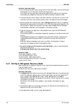
3.2.5 Setting of Refrigerant Recovery Mode
When carrying out the refrigerant collection on site, fully open the respective expansion valve of
indoor and outdoor units
All indoor and outdoor unit’s operation are prohibited.
[Operation procedure]
c
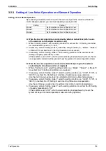
In
setting mode 2
with units in stop mode, set “B Refrigerant Recovery / Vacuuming mode”
to ON. The respective expansion valve of indoor and outdoor units are fully opened. (H2P
turns to display “TEST OPERATION” (blinks), “TEST OPERATION” and “UNDER
CENTRALIZED CONTROL” are displayed on the remote controller, and the indoor / outdoor
unit operation is prohibited.
After setting, do not cancel “Setting Mode 2” until completion of refrigerant recovery
operation.
d
Collect the refrigerant using a refrigerant recovery unit. (See the instruction attached to the
refrigerant recovery unit for more detal.)
e
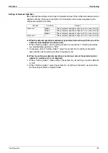
Press Mode button “BS1” once and reset “Setting Mode 2”.
Summary of Contents for VRV II RXYQ8MY1K
Page 53: ...Specifications Si39 502A 42 Specifications...
Page 143: ...Field Setting Si39 502A 132 Test Operation...
Page 258: ...Si39 502A Wiring Diagrams for Reference Appendix 247 FXCQ40M 50M 80M 125MVE 3D039557A...
Page 260: ...Si39 502A Wiring Diagrams for Reference Appendix 249 FXKQ25M 32M 40M 63MVE 3D039564A...
Page 264: ...Si39 502A Wiring Diagrams for Reference Appendix 253 FXMQ40M 50M 63M 80M 100M 125MVE 3D039620A...
Page 265: ...Wiring Diagrams for Reference Si39 502A 254 Appendix FXMQ200M 250MVE 3D039621A...
Page 266: ...Si39 502A Wiring Diagrams for Reference Appendix 255 FXHQ32M 63M 100MVE 3D039801C...
Page 267: ...Wiring Diagrams for Reference Si39 502A 256 Appendix FXAQ20M 25M 32M 40M 50M 63MVE 3D034206A...
Page 269: ...Wiring Diagrams for Reference Si39 502A 258 Appendix FXUQ71M 100M 125MV1 3D044973...
Page 270: ...Si39 502A Wiring Diagrams for Reference Appendix 259 FXAQ20MH 25MH 32MH 40MH 50MHV1 3D046348A...
Page 271: ...Wiring Diagrams for Reference Si39 502A 260 Appendix FXLQ20MH 25MH 32MH 40MH 50MHV1 3D046787A...
Page 272: ...Si39 502A Wiring Diagrams for Reference Appendix 261 BEVQ50MVE 3D046579A Notes...
Page 273: ...Wiring Diagrams for Reference Si39 502A 262 Appendix BEVQ71M 100M 125MVE 3D044901A Notes...
Page 285: ...Piping Installation Point Si39 502A 274 Appendix...
Page 293: ...Method of Replacing The Inverter s Power Transistors and Diode Modules Si39 502A 282 Appendix...
Page 307: ...Si39 502A iv Index...

