


Si39-502A
Field Setting
Test Operation
97
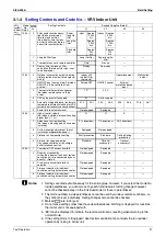
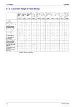
3.1.4
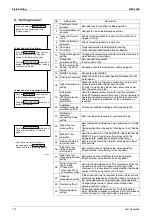
Setting Contents and Code No.
– VRV Indoor Unit
Notes:
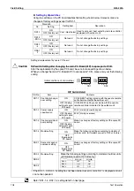
1. Settings are made simultaneously for the entire group, however, if you select the mode No.
inside parentheses, you can also set by each individual unit. Setting changes however
cannot be checked except in the individual mode for those in parentheses.
2. The mode numbers inside parentheses cannot be used by wireless remote controllers, so
they cannot be set individually. Setting changes also cannot be checked.
3. Marked
are factory set.
4. Do not make settings other than those described above. Nothing is displayed for functions
the indoor unit is not equipped with.
5. “88” may be displayed to indicate the remote controller is resetting when returning to the
normal mode.
6. If the setting mode to “Equipped”, heat reclaim ventilation fan conducts the fan residual
operation by linking to indoor unit.
VRV
system
indoor
unit
settings
Mode
No.
Note 2
Setting
Switch
No.
Setting Contents
Second Code No.(Note 3)
01
02
03
04
10(20)
0
Filter contamination heavy/
light (Setting for display
time to clean air filter)
(Sets display time to clean
air filter to half when there is
heavy filter contamination.)
Super
long life
filter
Light
Approx.
10,000
hrs.
Heavy
Approx.
5,000
hrs.
—
—
Long life
filter
Approx.
2,500
hrs.
Approx.
1,250
hrs.
Standard
filter
Approx.
200
hrs.
Approx.
100
hrs.
1
Long life filter type
Long life filter
Super long life
filter
—
—
2
Thermostat sensor in remote controller
Use
No use
—
3
Display time to clean air filter
calculation (Set when filter sign is not
to be displayed.)
Display
No display
—
12(22)
0
Optional accessories output selection
(field selection of output for adaptor for
wiring)
Indoor unit
turned ON by
thermostat
Operation output
Malfunction
output
1
ON/OFF input from outside (Set when
ON/OFF is to be controlled from
outside.)
Forced OFF
ON/OFF control
External
protection device
input
—
2
Thermostat differential changeover
(Set when remote sensor is to be
used.)
1°C
0.5°C
—
—
3
OFF by thermostat fan speed
LL
Set fan speed
—
—
4
Automatic mode differential (automatic
temperature differential setting for VRV
system heat recovery series cool/heat)
01:0
02:1
03:2
04:3
05:4
06:5
07:6
08:7
5
Power failure automatic reset
Not equipped
Equipped
—
—
13(23)
0
High air outlet velocity
(Set when installed in place with ceiling
higher than 2.7 m.)
N
H
S
—
1
Selection of air flow direction
(Set when a blocking pad kit has been
installed.)
F (4 directions)
T (3 directions)
W (2 directions)
—
3
Air flow direction adjustment (Set at
installation of decoration panel.)
Equipped
Not equipped
—
4
Field set air flow position setting
Draft prevention
Standard
Ceiling Soiling
prevention
—
5
Field set fan speed selection
(fan speed control by air discharge
outlet for phase control)
Standard
Optional
accessory 1
Optional
accessory 2
—
15(25)
1
Thermostat OFF excess humidity
Not equipped
Equipped
—
—
2
Direct duct connection
(when the indoor unit and heat reclaim
ventilation unit are connected by duct
directly.)
∗
Note 6
Not equipped
Equipped
—
—
3
Drain pump humidifier interlock
selection
Not equipped
Equipped
—
—
5
Field set selection for individual
ventilation setting by remote controller
Not equipped
Equipped
—
—
6
Field set selection for individual
ventilation setting by remote controller
Not equipped
Equipped
—
—
Summary of Contents for VRV II RXYQ8MY1K
Page 53: ...Specifications Si39 502A 42 Specifications...
Page 143: ...Field Setting Si39 502A 132 Test Operation...
Page 258: ...Si39 502A Wiring Diagrams for Reference Appendix 247 FXCQ40M 50M 80M 125MVE 3D039557A...
Page 260: ...Si39 502A Wiring Diagrams for Reference Appendix 249 FXKQ25M 32M 40M 63MVE 3D039564A...
Page 264: ...Si39 502A Wiring Diagrams for Reference Appendix 253 FXMQ40M 50M 63M 80M 100M 125MVE 3D039620A...
Page 265: ...Wiring Diagrams for Reference Si39 502A 254 Appendix FXMQ200M 250MVE 3D039621A...
Page 266: ...Si39 502A Wiring Diagrams for Reference Appendix 255 FXHQ32M 63M 100MVE 3D039801C...
Page 267: ...Wiring Diagrams for Reference Si39 502A 256 Appendix FXAQ20M 25M 32M 40M 50M 63MVE 3D034206A...
Page 269: ...Wiring Diagrams for Reference Si39 502A 258 Appendix FXUQ71M 100M 125MV1 3D044973...
Page 270: ...Si39 502A Wiring Diagrams for Reference Appendix 259 FXAQ20MH 25MH 32MH 40MH 50MHV1 3D046348A...
Page 271: ...Wiring Diagrams for Reference Si39 502A 260 Appendix FXLQ20MH 25MH 32MH 40MH 50MHV1 3D046787A...
Page 272: ...Si39 502A Wiring Diagrams for Reference Appendix 261 BEVQ50MVE 3D046579A Notes...
Page 273: ...Wiring Diagrams for Reference Si39 502A 262 Appendix BEVQ71M 100M 125MVE 3D044901A Notes...
Page 285: ...Piping Installation Point Si39 502A 274 Appendix...
Page 293: ...Method of Replacing The Inverter s Power Transistors and Diode Modules Si39 502A 282 Appendix...
Page 307: ...Si39 502A iv Index...


