


4 Web-based Switch Configuration
D-Link DGS-2000 Series Ethernet Switch User Manual
5
5
8
8
Click the
Find
button to locate a specific entry based on the information entered.
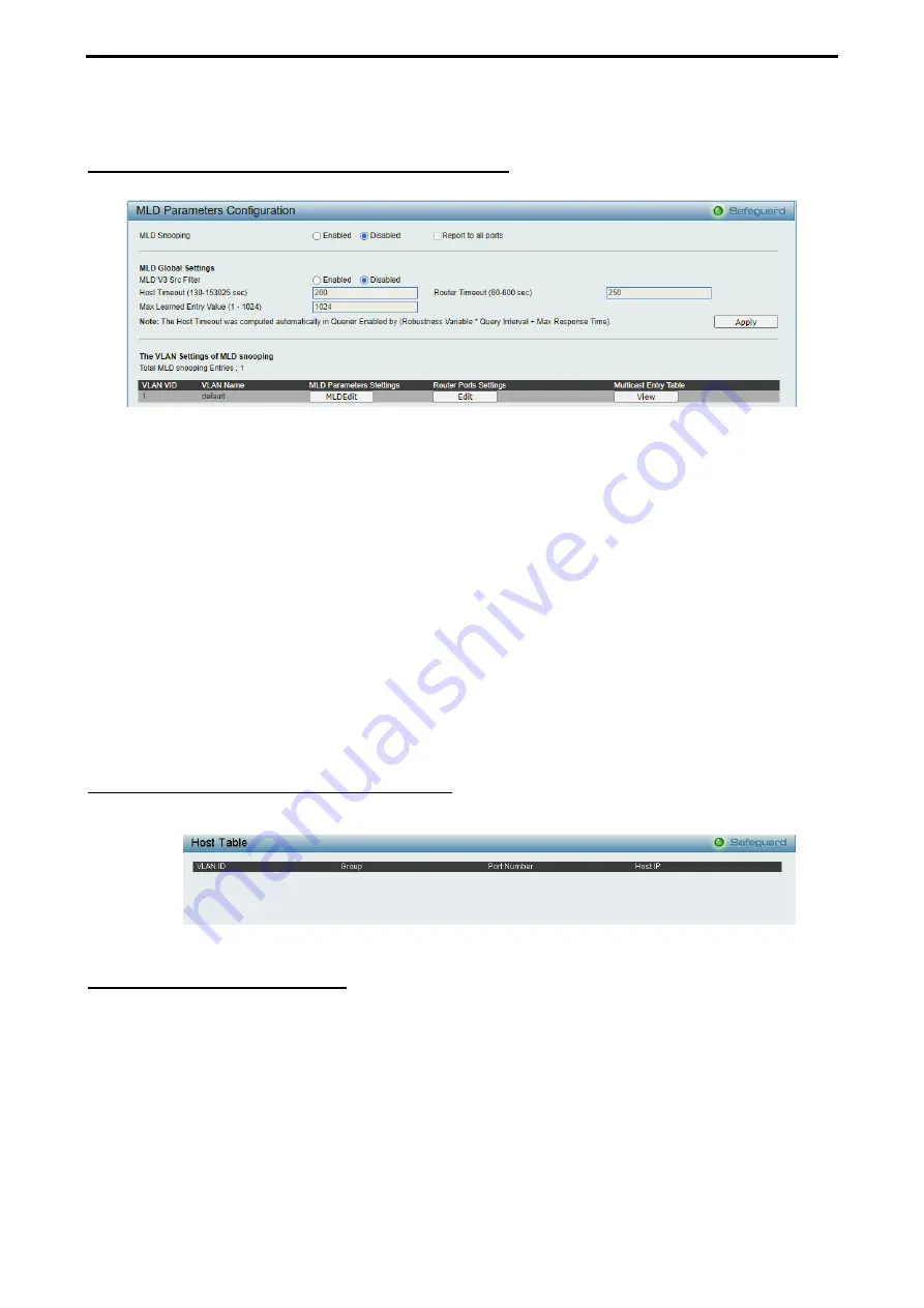
Configuration > MLD Snooping > MLD Snooping Settings
The MLD Snooping Settings page allows user to configure the max multicast group for IGMP Snooping.
Figure 4.72- Configuration > MLD Snooping > MLD Snooping Settings
MLD Snooping:
Enable or disable the MLD Snooping.
MLD Global Settings:
Host Timeout (130-153025 sec):
Specifies the time interval in seconds after which a port is removed from a
Multicast Group. Ports are removed if a Multicast group MLD report was not received from a Multicast port
within the defined
Host Timeout
period. The possible field range is 130 - 153025 seconds. The default
timeout is 260 seconds.
Router Timeout (60-600):
Specifies the time interval in seconds the Multicast router waits to receive a
message before it times out. The possible field range is 60 - 600 seconds. The default timeout is 125
seconds.
Max Learned Entry Value (1-1024):
Specifies the max learned entry value for MLD Snooping. The field
range is 1-1024. The default is 256.
Click
Apply
to make the configurations take effect. Press the
Edit
button under
Router Port Setting
, and
select the ports to be assigned for MLD snooping for the VLAN, and press
Apply
for changes to take effect.
Configuration > MLD Snooping > MLD Host Table
The MLD Host Table page displays the MLD Snooping information.
Figure 4.73- Configuration > MLD Snooping > MLD Host Table
Configuration > ISM VLAN Settings
In a switching environment, multiple VLANs may exist. Every time a multicast query passes through the
Switch, the switch must forward separate different copies of the data to each VLAN on the system, which, in
turn, increases data traffic and may clog up the traffic path. To lighten the traffic load, multicast VLANs may
be incorporated. These multicast VLANs will allow the Switch to forward this multicast traffic as one copy to
recipients of the multicast VLAN, instead of multiple copies.
Regardless of other normal VLANs that are incorporated on the Switch, users may add any ports to the
multicast VLAN where they wish multicast traffic to be sent. Users are to set up a source port, where the
multicast traffic is entering the switch, and then set the ports where the incoming multicast traffic is to be sent.
The source port cannot be a recipient port and if configured to do so, will cause error messages to be
produced by the switch. Once properly configured, the stream of multicast data will be relayed to the receiver
ports in a much more timely and reliable fashion.


