background image

28

 Chapter 2 – Introduction to Dolev 800V+/800V

2

/800V

3

Specifications

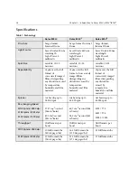
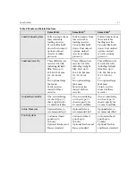
Table 1: Technology

Dolev 800V

+

Dolev 800V

2

Dolev 800V

3

Structure

Large-format, 
Internal Drum

Large-format, Internal 
Drum

Large-format, 
Internal Drum

Light Source

Laser Diode 650 nm 
wavelength
Light Power 5 
milliwatts

Laser Diode 650 nm 
wavelength
Light Power 5 
milliwatts

Laser Diode 650 nm 
wavelength
Light Power 5 
milliwatts

Spot Size 

variable, 10-25 
microns 

variable, 10-25 
microns 

variable, 10-25 
microns 

Repeatability

±

5µm

 ο

ver the full 

format of 
successively imaged 
films, disregarding 
any distortion caused 
by temperature, 
humidity and film 
material.

±

5µm


over the full 

format of successively 
imaged films, 
disregarding any 
distortion caused by 
temperature, 
humidity and film 
material.

±

5µm


over the full 

format of 
successively imaged 
films, disregarding 
any distortion 
caused by 
temperature, 
humidity and film 
material.

Spinner

Air bearing up to 
24,000 rpm

Air bearing up to 
45,000 rpm

Air bearing up to 
45,000 rpm

Raw Imaging Speed

@100 lpmm/ 2540 dpi

@ 80 lpmm/ 2032 dpi

@ 50 lpmm/ 1270 dpi

37.27 cm

2

/second 

(346 in

2

/min)

89.3 cm

2

/second

(831 in

2

/min)

60.7 cm

2

/second (564 

in

2

/min)

94.9 cm

2

/second (882 

in

2

/min)

4995 / 774

6283 / 974 

10053 / 1558

Throughput

(full formats per 
hour)

(full formats per 
hour)

(full formats per 
hour)

@100 lpmm/ 2540 dpi

10 full formats/hr 
(80 A4 pages/hr)

16.2 full formats/hr 
(130 A4 pages/hr)

23 full formats/hr 

@ 80 lpmm/ 2032 dpi

12 full formats/hr 
(96 A4 pages/hr)

21.4 full formats/hr 
(171 A4 pages/hr)

27 full formats/hr 

Summary of Contents for Dolev 800V+

Page 1: ...www creo com User Guide English Dolev 800V 800V2 800V3 399Z1R557B...

Page 2: ......

Page 3: ...Dolev 800V 800V2 800V3 User Guide...

Page 4: ......

Page 5: ...or registered trademarks of Microsoft Corp Xerox is a registered trademark of Xerox Corp Other brand or product names are the trademarks or registered trademarks of their respective owners FCC Compli...

Page 6: ...9 458 5 367 360 5 384 648 5 384 899 5 412 491 5 412 737 5 420 702 5 420 722 5 459 505 5 473 733 5 481 379 5 488 906 5 497 252 5 508 828 5 509 561 5 517 359 5 519 852 5 526 143 5 532 728 5 561 691 5 56...

Page 7: ...20 Shutdown 20 Reset Button 21 Control Panel 21 LCD Screen 22 Soft Buttons and Soft Functions 24 Main Screen Soft Functions 25 Specifications 28 3 Media Management 35 Overview 36 The Supply Cassettes...

Page 8: ...8 Film Specifications 59 Imaging 59 Chemistry 60 Film Handling 60 Dimensions 61 Preparing Exposure Strips 61 Exposing the Strips 64 Measuring the Density on the Exposed Strips 64 Recording New Laser I...

Page 9: ...Using This Manual Who Should Use This Manual viii...

Page 10: ...hese are followed by the Control Panel description and the imagesetter specifications Chapter 3 Media Management explains how to unload the supply cassette load film into it and load it back into the...

Page 11: ...Read this chapter carefully before installing operating or maintaining the Dolev 800V 800V2 800V3 imagesetter Installation Safety Precautions 2 General Safety Precautions 2 Laser Safety Precautions 4...

Page 12: ...r must be disconnected switched to 0 position Lithium Battery The Dolev 800V 800V2 800V3 contains a Lithium battery in the CPU board The battery should be replaced by qualified service personnel The b...

Page 13: ...tors and deacivate the laser It may take up to 30 seconds for the spinner motor to halt after a door is opened Wait 30 seconds from the time the door is opened before you dismantle the internal side p...

Page 14: ...so Refrain from tampering with the electrical wiring inside the imagesetter While the Imagesetter is switched on and the interlocks are defeated There is power present in the electrical optical and m...

Page 15: ...n the Output optical connector of the Static optics assembly Dynamic optics assembly Optical fibers Optical fibers connectors and on the inside of the imagesetter drum Up to 10 milliwatt of laser powe...

Page 16: ...rsonnel if any of them are missing or damaged K2G954 K2G955 K2G956 DANGER LASER LIGHT WHEN OPEN AND INTERLOCK DEFEATED AVOID EXPOSURE TO BEAM CAUTION HANDS OFF UNTIL SPINNER MOTOR HAS RESTED WAIT 30 S...

Page 17: ...K8F711 CLASS 1 LASER PRODUCT EN60825 21CFR 1040 DANGER LASER LIGHT WHEN OPEN AND INTERLOCK DEFEATED AVOID EXPOSURE TO BEAM SEE INSTALLATION INSTRUCTIONS BEFORE CONNECTING TO THE SUPPLY DANGER LASER L...

Page 18: ...apter 1 Safety Precautions K8F712 374A7B951 374A30170 374A2G961 LASER LIGHT CONDUCTED THROUGH OPTICAL FIBERS AVOID EXPOSURE TO BEAM DANGER Electrical hazard Choc electrique Elektroschockgefahr 374A301...

Page 19: ...re 1 Dolev 800V3 left side door open K2G954 K2G956 K2G958 K2G955 K8F711 Internal Side Protective Barrier K2G956 attached on the fiber of static optic near optical connector Fiber connector locker 290F...

Page 20: ...10 Chapter 1 Safety Precautions Figure 2 Right side door open Figure 3 Right side internal protective barrier removed K2G954 374A7B951 374A30170 K2G958 K2G955 K8F711 K8F711 same on left side...

Page 21: ...Warning Labels 11 Figure 4 Rear view K2G957 K1F658...

Page 22: ......

Page 23: ...Introduction to Dolev 800V 800V2 800V3 Introduction to the Imagesetter 14 Imagesetter Front View 15 Imagesetter Rear View 18 Startup 20 Shutdown 20 Reset Button 21 Control Panel 21 Specifications 28...

Page 24: ...sure are controlled by the Dolev 800V 800V2 800V3 micro controller A punch option allows you to define customized registration marks This function is especially important when preparing film for impos...

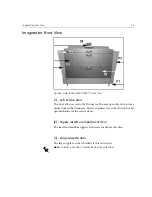
Page 25: ...door to clear media stuck in the drum area Service engineers access the electronics and optomechanics via the service doors 2 Supply cassette compartment door The small and medium supply cassettes are...

Page 26: ...llows access to the Drum area You may open this door to clear media stuck in the drum area Service engineers access the electronics and optomechanics via the service doors 6 Output cassette door The o...

Page 27: ...34 inch in one inch step intervals Figure 7 Dolev 800V 800V2 800V3 Small and Medium Cassettes A Small supply cassette This is a 12 inch wide cassette for film widths 10 11 and 12 inch B Medium supply...

Page 28: ...nel is not removed 2 In line processor panel not shown Remove the panel if you connect to the in line processor 3 Lower service panel Use the panel to access the power distribution unit and the vacuum...

Page 29: ...ome other electrical problem has shorted power to the imagesetter check the breaker 9 Vacuum pump outlet Outlet for vacuum pump Turbo Screening connection The Turbo Screening board is connected via a...

Page 30: ...rking at all times you do not need to turn off the power overnight If you intend to leave the imagesetter idle for 48 hours turn off the imagesetter Press the On Off switch to turn off the imagesetter...

Page 31: ...esetter is not responding to commands depress the Reset button to resume work Control Panel The Dolev 800V 800V2 800V3 sends the imagesetter options status and error messages to the Control Panel The...

Page 32: ...section on the previous page LCD Screen The LCD screen displays a variety of text such as messages and graphical representations such as icons and imagesetter views that inform you of the current stat...

Page 33: ...ready to expose i e film is already loaded and both the Loading and Unloading drawers are closed NOT READY appears when the imagesetter is not ready to expose for example film is not loaded or one of...

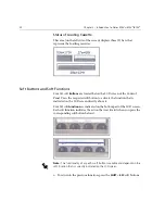
Page 34: ...requested soft button to activate the function that is indicated on the LCD screen directly above it Four 4 soft Functions are indicated on the bottom part of the LCD screen Each soft function indica...

Page 35: ...this option to indicate whether you wish to use one or two large cassettes Press the soft button To Abort Stop the current process Status View system messages Params View the parameters of the last cu...

Page 36: ...the loaded film is a full roll If you did not load a full roll of film enter the current length in meters This is the only field that updates during exposure Material Film Plate Paper Film Toggle this...

Page 37: ...ls Operation The tools operation are tools for service engineer Full Length 0 63 61 Enter the length of a full roll of film Note If you loaded a full roll of film this value is identical to that of Cu...

Page 38: ...of successively imaged films disregarding any distortion caused by temperature humidity and film material 5 m over the full format of successively imaged films disregarding any distortion caused by te...

Page 39: ...02 MAN Roland 100 200 600 Komori 26 28 44 Heidelberg GTO SM52 SM74 SM102 MAN Roland 100 200 600 Komori 26 28 44 Resolution 50 200 pixels mm 1270 5080 dpi continuously variable Optional lower and highe...

Page 40: ...film or polyester plates Roll medium to high contrast red sensitive film or polyester plates Roll medium to high contrast red sensitive film or polyester plates Media Width 254 863 mm in steps of 25...

Page 41: ...ht film Sizes up to 304 508 863 mm 12 20 34 in or Two optional large 863 mm 34 in cassettes instead of three cassettes Three different size cassettes for rolls including daylight film Sizes up to 304...

Page 42: ...Power Less than 3 KVA Operating Environment Temperature Relative Humidity Audible Noise Heat Dissipatoin 23 C 3 C 73 4 F 5 4 F 55 5 RH 55dbA 2500 BTU hr 23 C 3 C 73 4 F 5 4 F 55 5 RH 55dbA 2500 BTU hr...

Page 43: ...ystem AIX Architecture CPSI with composite workflow and Turbo Screening CPU Speed 332 MHz and up Interpreter Postscript Levels 2 and 3 DataFormats PDF Postscript EPS DCS1 DCS2 TIFF IT PI CopyDot scann...

Page 44: ...d film LW CT ICF Imposition Control File Communication Formats Appletalk TCP IP Macintosh platform Power Macintosh 604 604e with Apple OS 7 5 3 or higher RIP Software type Adobe CPSI with composite wo...

Page 45: ...nto a supply cassette and inserted into the imagesetter You can select one of three supply cassettes a small 12in medium 20in or large 33in cassette Overview 36 The Supply Cassettes 38 Set Loading Aut...

Page 46: ...nctions by moving through a tree like series of menus on the host computer screen All the functions can also be accessed through the imagesetter Control Panel The Dolev 800V 800V2 800V3 has an automat...

Page 47: ...on The media is exposed and ejected The ejected media is sent to the output cassette or to an optional inline processor The following figure shows the media path in the imagesetter Figure 11 Dolev 800...

Page 48: ...he supply cassette Loading the supply cassette into the imagesetter Performing Set Loading and Cassette Sign In Using Two Large Cassettes The option to use two Large cassettes enables higher efficienc...

Page 49: ...1 To unload either the small 12 inch or medium 20 inch cassette open the Supply cassette compartment door 1 and push back the locking bar 2 Figure 12 Unloading the Small or Medium Supply Cassette 2 Re...

Page 50: ...e 1 Check that the film you intend to load on the cassette is in the darkroom before you lock the door and turn off the lights 2 Close and lock the door to the darkroom 3 Turn on the bright cyan light...

Page 51: ...tached to the spool namely the fixed flange and the removable flange Figure 15 Lifting the Film Spool out of the Supply Cassette 1 Inch film lead Film Emulsion side down Supply cassette opening latch...

Page 52: ...10 Lower the spool into the cassette so that its ends fit between the prongs of the cradle Allow approximately 1 inch of film to stick out over the edge of the cassette 11 Check that the film is strai...

Page 53: ...tte 3 4 so that the film extends from the bottom of the cassette toward the rear of the imagesetter that is away from you 3 Fold down the cassette handles 5 Pull the locking bar forward Figure 17 Load...

Page 54: ...2 Place the cassette on the inner door and slide the cassette 3 into place Figure 18 Loading the Large Cassette 3 Fold down the cassette handles 4 and close the inner cassette door 4 Close the Large...

Page 55: ...Panel as explained on the following page or via the host workstation Performing Set Loading via the Control Panel 1 At STANDBY press the Util soft button The Utilities menu appears the pointer cursor...

Page 56: ...te into the imagesetter you must Sign In the cassette Cassette Sign In records the type of media manufacturer batch number and the length of media on the cassette The information is used to automatica...

Page 57: ...film or polyester plate c Select the media thickness 4 mil or 7 mil d Register the initial length of the media on the cassette If the cassette contains less than a full roll of film modify the length...

Page 58: ...t Cassette Press the handle 1 on the imagesetter Output cassette door 2 and open the door Figure 19 Unloading the Output Cassette Note The imagesetter may output film to an output cassette or through...

Page 59: ...re allowed to feed each subsequent film When you have fed the last film into the processor and received the signal that the feed is complete you may unlock the door 6 Load the output cassette back int...

Page 60: ...flange of the Dolev 800V 800V2 800V3 drum To assist Creo and the customer in the punch system definition Punched Film Layout form has been prepared The customer and the Creo engineer should complete a...

Page 61: ...of used film slugs from the system Three blasts of compressed air are used to achieve this The film slugs are collected into a large black hose located near the unloading cassette You should empty th...

Page 62: ...0 H Center Height 558 W Center Width NVM screen Cri Service Tables Punch Settings Drag a full format file on an expose template request bottom center alignment to the punch with a 10 0 mm offset from...

Page 63: ...define the punch alignment parameters To define the punch parameters 1 Click the Punch check box The Params button next to it is enabled 2 Click Params The Punch dialog box appears The options that a...

Page 64: ...image to be the reference point for example the top left when you position the image relative to the punch If you select None or External you will not be able to define an offset Offset from punch Def...

Page 65: ...e film relative to the expose area 4 From the Alignment list box select an alignment option The R icon reflects your selection 5 In the Offset Vertical and Horizontal boxes type the distance of the re...

Page 66: ...t breaker at the lower rear side of the imagesetter 2 To access the inside of the imagesetter drum area open the left or right service door or both side doors to do so unscrew the thumb screw s access...

Page 67: ...Res Intensity Calibration Preparing Exposure Strips 61 Exposing the Strips 64 Measuring the Density on the Exposed Strips 64 Recording New Laser Intensity Values 64...

Page 68: ...thick and small text may be covered In addition the life of the laser is shortened To calibrate laser intensity perform the following steps for each exposure resolution 1 Prepare exposure strips 2 Se...

Page 69: ...Imaging Figure 20 Film spectral sensitivity and characteristic curve Attribute Specification Wavelength 633 670 nm Image Quality Dot Production 2 98 150 line screen 1 99 150 line screen with correctio...

Page 70: ...of the roomlight packaging might not withstand those extreme values If such an extreme condition was faced the roomlight packages should be visually checked If the edge tape is loose the film might ha...

Page 71: ...ion 1 Access the Remote mode of the imagesetter The Util Main screen appears 2 Select Expose from the Util Main screen the Expose menu opens 3 Select Intensity Strips from the Expose menu to define th...

Page 72: ...1000 20 Enter the height of the intensity strips in mm for example 5 Strip Width 0 1180 700 Enter the width of the intensity strips in mm for example 100 Cassette SML Toggle to the size of cassette c...

Page 73: ...e strip repeat the entire procedure for each resolution Note If you wish to use Half Resolution set the Half Res field in exposure format in the Host to Yes and begin the exposure process from the beg...

Page 74: ...ich exposed strip has the best density look at the light strip that is exposed together with the black strip Ideally the transparent area should be 0 and the black area should be 100 4 Write down the...

Page 75: ...tons 5 Modify the values for the active table as follows Material toggle field default is Film Leave this field as Film Vendor toggle field default is None Leave this field as None Media Thickness def...

Page 76: ......

Page 77: ...Data Configuration Setting Data Connectivity 68 Accessing the Output Device Configuration 70 Configuring the Dolev 800V 800V2 800V3 Imagesetters 74...

Page 78: ...v and the Brisque Following are the locations of the TSP boards on the Dolev 800V3 Connecting TSP Cables Dolev 800V3 WARNING Do not connect the TSP cables unless the Dolev 800V 800V2 800V3 is switched...

Page 79: ...p n 199D06226 link between the Brisque and a Dolev 800V3 1 Connect the cable marked TSP to the TSP Board on the Brisque see table on page 68 2 Connect the other end of the TSP cable to connector COM...

Page 80: ...utput Devices Handling window appears The Output Device Handling Window From the Output Devices Handling window all configurations of the output devices are performed From here new devices are configu...

Page 81: ...Accessing the Output Device Configuration 71 Figure 23 Output Devices Handling window Device Section Operations Section Configured Device default Collapse Expand button...

Page 82: ...e Expand or Collapse icon Click to expand or collapse the entire list of devices to show or hide all details New Click to open the New Device Wizard and start configuring a new device Modify Click to...

Page 83: ...he output devices are activated from here Operations are enabled when a particular configuration is selected Some operations are connection specific others are applicable to all output devices Set as...

Page 84: ...row next to the Dolev icon If a Dolev is configured the connection to the Brisque is displayed under the Dolev icon the name is in green if it is the default imagesetter To configure a new Dolev 800V...

Page 85: ...Configuring the Dolev 800V 800V2 800V3 Imagesetters 75 4 Click Next a device summary is displayed Now the Device Type is identified as Dolev800V3...

Page 86: ...ev 800V 800V2 800V3 imagestter parameters 1 From the Output Devices Handling window select the Dolev imagesetter configuration and click Modify the following dialog box opens The Device Model name for...

Page 87: ...s The modified connection is displayed in the Output Devices Handling window under the Dolev icon To delete the Dolev 800V 800V2 800V3 imagesetter configuration 1 From the Output Devices Handling wind...

Page 88: ...t the Dolev configuration 2 Click Reconfigure The Brisque reads the data from the device and confirms the connection It displays a confirmation dialog for a few seconds if the device has been reconnec...

Page 89: ...ding unloading assembly 3 4 Lower service panel 18 M Master circuit breaker 19 20 56 Media types 14 Medium supply cassette 17 Minimum film feed 54 Move Carriage 62 O On Off switch 20 Optical fibers 5...

Page 90: ...ification 34 punch system 31 repeatability 28 resolution 29 screen 29 site area 32 speed 28 spinner 28 spot size 28 structure 28 unloading cassette 31 Troubleshooting 56 58 Turbo screening connection...

Reviews: