background image

8 of 64

CORRADI S.R.L.

 - INSTALLATION MANUAL - PERGOTENDA ® MAESTRO

REV.1 - 11.2019

CONTENTS

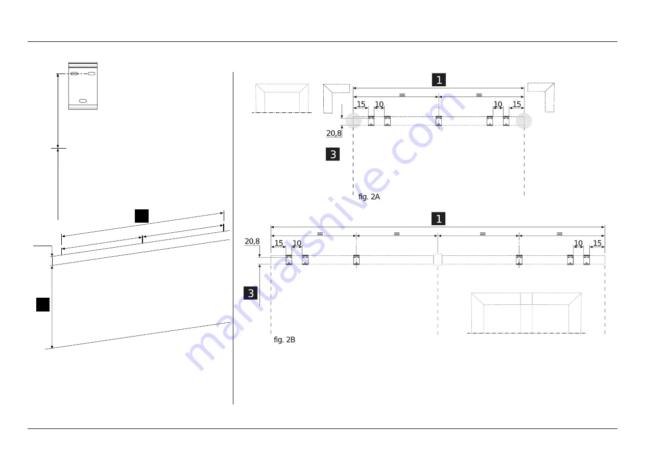
1 WALL INSTALLATION

fig. 1


- Trace on the wall

-  the slot fixing lin

e at the height indicated in the project drawing 

(

3

) + 20.8 cm;

-  the external line of the total width (

1

);

-  in case of side-by-side structures, trace the intermediate fixing 

measures of the central brackets.

FLOOR

HEIGHT UNDER BEA

M

fig. 2A


-   Plate-to-wall fixing drawing for single module.

fig. 2B


-   Plate-to-wall fixing drawing for side-by-side module.

Ex

ter

nal side

Ex

ter

nal side

Ex

ter

nal side

Ex

ter

nal side

Central

pillar

HEIGHT UNDER BEA

M


Summary of Contents for PERGOTENDA MAESTRO

Page 1: ...MAESTRO PERGOTENDA Installation manual ...

Page 2: ......

Page 3: ...ng with technical changes etc performed during the warranty period voids the warranty immediately CORRADI S r l reserves the right to apply technical changes to the components or the product except for the main features at any time and without notice INSTALLATION MANUAL TRANSLATION OF THE ORIGINAL INSTRUCTIONS CONTENTS SYMBOLS 4 CONTROLS AND VERSIONS 6 MATERIAL CHECK UNPACKING AND PREPARATION 7 1 ...

Page 4: ...ectricians etc must have the specific skills and mental and physical requirements necessary to perform the assigned tasks Upon installation always perform preventive checks of the correct assembly operation and efficiency of the manual and electric controls According to the profile length and weight handle the same with the help of the suitable number of operators specified by the regulations Atte...

Page 5: ... otherwise specified are expressed in centimetres PRELIMINARY CHECKS When receiving the packed goods and before proceeding with the installation check the material integrity and the presence of all components necessary for the installation Thoroughlyfollowtheinformationprovidedintheparagraph Materialcheck unpackingandpreparation STORAGE AND MAINTENANCE The packed components must be handled followi...

Page 6: ...ove the screw on the rear side of the remote control and replace it with a similar model 12 Vdc alkaline battery mod 23 AE Replacement of the remote control battery 2 This transmitter is supplied by a 3 Volt CR2032 battery To replace the battery open the flap on the rear side slide out the exhausted battery and replace it with a new one respecting the polarity Then fit the flap in the relevant sea...

Page 7: ...spond to the ones you have The packages contain the elements and accessories required for the installation and the User manual Packages weighing between 25 kg and 55 kg must be handled by at least two people Proceed as follows remove the components from the packages Note there are no retaining elements like screws and dowels since they must be decided by the installer according to the type of moun...

Page 8: ...ect drawing 3 20 8 cm the external line of the total width 1 in case of side by side structures trace the intermediate fixing measures of the central brackets FLOOR HEIGHT UNDER BEAM fig 2A Plate to wall fixing drawing for single module fig 2B Plate to wall fixing drawing for side by side module External side External side External side External side Central pillar HEIGHT UNDER BEAM ...

Page 9: ...NUAL PERGOTENDA MAESTRO REV 1 11 2019 CONTENTS 1 WALL INSTALLATION External side External side Fig 3 Use a water level to check the linearity of the drawn traces Fig 4 Position the brackets on the line on the wall and mark the fixing holes ...

Page 10: ...REV 1 11 2019 CONTENTS 1 WALL INSTALLATION Fig 5 Drill the fixing holes of the brackets on the wall using a suitable bit Fig 6 Insert the dowels suitable to the wall and the loads see table on page 51 tighten the screws check the planarity of every single bracket ...

Page 11: ...the project indicates a side by side module use the bracket B as central component by fixing it to the wall following the operations described before NOTE in case of side pillar the wall mounted bracket is not present Fig 8 Bracket fixing to wall for central pillar fix the central pillar for wall installation A to plate B using 6 M8x16 screws C A C HEIGHT UNDER BEAM B ...

Page 12: ... the parallelism and diagonals referring to the 4 holes at the corners of the ground plate ATTENTION TO THE INSTALLATION The foot sides with the holes for the pillar retaining screws are those of side PROJECTION In case of floor water drain before fastening to the ground trim the punched sticker with a cutter in the area of the drain hole and apply a bead of silicone in the hole as shown in Det X ...

Page 13: ...wels suitable to the floor In doing this respect the parallelism and diagonals measures referring to the 4 holes at the corners of the ground plate ATTENTION TO THE INSTALLATION The foot sides with the holes for the pillar retaining screws are those of side PROJECTION In case of floor water drain before fastening to the ground trim the punched sticker with a cutter in the area of the drain hole an...

Page 14: ...TTENTION TO THE INSTALLATION for the side pillars the foot sides with the screw fixing holes of the pillar are those of the PROJECTION side Y whereas for the common central pillars the foot sides with the holes for the pillar fixing screws are those of the WIDTH side Z In case of floor water drain before fastening to the ground trim the punched sticker with a cutter in the area of the drain hole a...

Page 15: ...ead of silicone in the pillar foot areas as shown in det Y Fig 14 Fix the pillars to the feet using M8x16 BUTTON screws A q ty 4 each Note Should it not be possible to reach the screws because the pillar is against a wall after the structure installation it is COMPULSORY to use the wall mounting system on the upper beam A B A B A B A A Det X C Det Y IMPORTANT the 4 pillars must be positioned so as...

Page 16: ...ILLAR INSTALLATION SELF SUPPORTING VERSION WITH SUPPLEMENTARY MODULE ON WIDTH SIDE SELF SUPPORTING VERSION WITH SUPPLEMENTARY MODULE ON PROJECTION SIDE Det X Det X Fig 15 Repeat the operations described in figures 13 and 14 following the installation drawings described in this image det X ...

Page 17: ...d with the brackets fixed by Corradi S r l for a possible side closure Z Fig 17 Wall mounted beam assembly Note before installing the beams to the wall install profile A Fix profile A with the suitable short self drilling screws B at a distance of approximately 50 cm one from the other det X ATTENTION If side closures are foreseen to be installed on the lateral sides it will be necessary to cut th...

Page 18: ...ESTRO REV 1 11 2019 CONTENTS Fig 18 Lay the beam A on the brackets B fixed to the wall 3 CROSSBEAM INSTALLATION A B B B WALL MOUNTED VERSION Fig 19 Anti lifting bracket assembly Note the anti lifting plate is foreseen to be fixed on the 4 side brackets A A A ...

Page 19: ... assembly Fix the plate A to the wall mounted bracket B using the 2 supplied M8x16 screws C Fig 21 Side beam assembly Note before the installation check that the pillars are positioned correctly see page 12 Insert the side beam A in the rear brackets B and the screws C in the relevant slots D see det X Y A A C B B C A WALL MOUNTED VERSION Det Y Det X A C D B ...

Page 20: ...REV 1 11 2019 CONTENTS Fig 22 Side beam assembly Tighten the M8x16 screws A to the side beam det X tighten without forcing the screws B to the pillar det Y repeat the operations on the opposite side WALL MOUNTED VERSION Det Y A Det X A A B 3 CROSSBEAM INSTALLATION ...

Page 21: ...CROSSBEAM INSTALLATION SELF SUPPORTING VERSION WITH SUPPLEMENTARY MODULE ON WIDTH SIDE fig 23 Main diagram Det B Det A Det E Det D Det C CENTRAL BEAM WIDTH SIDE 1 PROJECTION SIDE 1 2 1 2 1 5 4 3 3 PROJECTION SIDE 1 PROJECTION SIDE 2 PROJECTION SIDE 2 WIDTH SIDE 1 WIDTH SIDE 2 WIDTH SIDE 2 ...

Page 22: ...SBEAM INSTALLATION SELF SUPPORTING VERSION WITH SUPPLEMENTARY MODULE ON PROJECTION SIDE fig 24 Main diagram Det B Det A Det E Det D Det C CENTRAL BEAM PROJECTION SIDE 1 WIDTH SIDE 2 2 1 2 1 5 4 3 4 5 PROJECTION SIDE 2 PROJECTION SIDE 1 PROJECTION SIDE 2 WIDTH SIDE 2 WIDTH SIDE 1 WIDTH SIDE 1 ...

Page 23: ... 3 CROSSBEAM INSTALLATION Fig 25 Insert the first crossbeam A into pillars B by inserting without tightening det X the three screws C into the slotted seats D Note Use the same method for the following crossbeams A B B C D Det X C The roller tube seat must be kept outside the structure ...

Page 24: ... unit A on the relevant screws B which have been previously screwed to the motor bearing crossbeam C and then tighten them introduce the cable D inside the slot on the motor bearing crossbeam routing it out of the crossbeam side in the direction where it will be connected to the control unit A A A A B C C D D 3 CROSSBEAM INSTALLATION ...

Page 25: ...tor cable coming out of the beam inside the pillar through hole B We recommend that pillar to be the one with the power supply for the structure Fig 28 From the accessories box take the 16 M8x16 BUTTON screws needed to fix the beam and the pillar insert the 4 screws A through the inspection hole on each pillar without fully tightening them leave a few millimetres to allow the following installatio...

Page 26: ...he IMPACT runners will allow the following positioning of the canvas lifting kit and therefore they must be inserted towards the inside of the structure and slid close to the motor side A A A B C B B B C C Fig 30 Position the runners with their ends at 1 5 cm from the motor crossbeam fix the top part of runners A with plates B by screwing them with self drilling screws C Position the plates at app...

Page 27: ...installed on the side of the beam see page 24 fit the central runner A in the lower screw B on the crossbeam then tighten the upper screw C AFTER INSTALLING THE MOTOR SHAFTS fit the RH LH casings D and fix them with the relevant self drilling screws AFTER INSTALLING THE MOTOR SHAFTS fit the central casing D and fix it with the relevant self drilling screws A B C E D Y ...

Page 28: ...ve the runner drive slider against the limit switch towards the motor in order to group all intermediate sliders at limit stop Fig 33 Shaft installation Slide shaft A into the motor hexagon shaft B if the two shafts do not match male and female slightly rotate shaft A keeping it against the motor until the first engagement point tighten screw B A B B B ...

Page 29: ... A keeping it against the motor until the first engagement point tighten screw B A B Note to set the motor refer to the instructions provided inside the control unit box otherwise you can find them in the reserved area of the CORRADI EU website Fig 35 Shaft installation Perform a general tightening check of the motor shaft screws Check that the movements are correct by temporarily connecting the e...

Page 30: ...TION MANUAL PERGOTENDA MAESTRO REV 1 11 2019 CONTENTS 7 CONTROL UNIT INSTALLATION Fig 36 Connect the motor cable connector to the control unit C det X then place it inside the pillar det Y with internal reinforcement Det Y Det X C C ...

Page 31: ...l runner from bending during the lifting Start by inserting the front terminal tube D1 on the first slider C1 then insert the other tubes except the last terminal on motor side D2 Activate the awning closure by moving the already inserted sliders closer to the last fixed one C2 Then fit the terminal tube D2 on slider C2 and tighten the retaining nut Adjust the limit switches see relevant chapter a...

Page 32: ... apply Apply a strip of double sided adhesive tape A with the same length of the cover casing B under the motor cable inlet slot make the cover casing B perfectly adhere against the double sided adhesive tape A Note in presence of EXPERIENCE lights on the canvas this casing must be installed exclusively after the lights installation in order to use the cable passage on the second slot of the casin...

Page 33: ...AL PERGOTENDA MAESTRO REV 1 11 2019 CONTENTS 10 MOBILE GUTTER Fig 39 fix the plate on both MOBILE GUTTER PLUGS NOTE see page 56 to bring the spring against the mobile gutter FOLDED AWNING SIDE FIXED GUTTER MOBILE GUTTER CURVED CANVAS SPACERS ...

Page 34: ...e bottle in the middle until it breaks 3 then dampen the top of the block and apply remove a small part of external adhesive tape cover 4 for the GUTTER PLUG 2 installation insert the indicated side of the GUTTER PLUG 2 in the end of the gutter profile 1 with a slight rotation until it is fully engaged then remove the remaining adhesive tape cover 4 press to ensure perfect adherence to the gutter ...

Page 35: ...11 2019 CONTENTS Fig 41 Insert a 3 mm shim in the relevant GUTTER PLUG seat 1 until fully home 2 Fig 42 Apply silicone along the profile GUTTER PLUG junction line as shown in the figure Note repeat these operations on the structure opposite side 1 2 2 1 10 MOBILE GUTTER ...

Page 36: ...t the lower striker bracket 1 at the end of the terminal tube seat 2 by rotating it as shown in detail X fit the upper striker plate 3 in the internal profile of gutter 4 by rotating it as shown in detail Y tighten screw 5 close to the terminal tube see detail Z the external screw 6 with dead hole allows adjusting the gutter height see detail W repeat the operation on the opposite side 1 2 1 2 X Y...

Page 37: ...suring that the gutter does not scrape first drill the gutter two ends then its central part at steps of approximately 50 cm in the suitable groove and the terminal tube with a ø4 bit Fig 46 Use the suitable rivets to fit the gutter in the previously drilled points repeat these operations symmetrically on the structure opposite side 10 MOBILE GUTTER ...

Page 38: ...ure each gutter profile Fig 48 After fitting all perimeter gutters and securing them with small seal parts tighten the structure screws to make the gutters better adhere to the pillars proceed with the final installation of the perimeter seals A having care to position the seal lip downwards ATTENTION a wrong positioning of the seal could lead to seepage problems A NOTE Before fitting gaskets care...

Page 39: ...ng care to follow the cutting line on the plastic component Note IMPORTANT Each structure must feature at last 2 out of 4 drainage pillars A Det X Fig 50 Note apply silicone under the plastic component before the installation to avoid any leak We recommend applying silicone also inside the gutter before positioning the plastic component silicon must be applied in all cases regardless if the pillar...

Page 40: ...1 11 2019 CONTENTS 12 SUPPORTING PROFILE INSTALLATION Fig 51 If SCREEN is not to be installed on the side close the gap with the suitable profile A Det X fix the profile with the suitable short self drilling screws B by placing one every 100 cm approximately A Det X B ...

Page 41: ... B on the pole using the supplied Button screws 3 Insert the pole first to the ground and then bring the upper plate against the profile 4 Fix the upper plate using the short self drilling screws keeping the pole perfectly vertical 5 Fit the SCREEN support plate C using the short self drilling screws keeping it aligned to the pillar side surface 13 SUPPLEMENTARY PILLAR A A B C B ...

Page 42: ...enfortheSCREENclosureinstallation installthesuitableconnectionsontheinternal sides the motor support A on the pillar or on the intermediate pillar and the idle pin support B on the opposite pillar C Fig 54 Fit brackets C fully home on both sides with short self drilling screws in the areas indicated in the figure B A SILICONE C C ...

Page 43: ...l runners on the pillars as shown in det X proceed with the closure assembly as indicated in the MAGIKO BRIO manual NOTE install the runner at approx 4 5 mm from the outer edge of the pillar NOTE the side runners must be installed with the mobile profile outside contrary to what described on the MAGIKO BRIO installation manual B 14 SCREEN INSTALLATION Det X A G1 LH 4 5 mm G1 RH External External ...

Page 44: ...RADI S R L INSTALLATION MANUAL PERGOTENDA MAESTRO REV 1 11 2019 CONTENTS 14 SCREEN INSTALLATION Fig 56 The wirings must be distributed on the perimeter using the channels by introducing them into holes A and B B A ...

Page 45: ...ESTRO REV 1 11 2019 CONTENTS Fig 58 Configuration without SCREEN 4 Ways Doors Screw using short self drilling screws A A Fig 57 Configuration with or without SCREEN 2 Ways 2 Doors Screw using short self drilling screws A A 15 SLIDING GLASS DOORS INSTALLATION ...

Page 46: ...ix the additional safety block A to the cover B of the beam in correspondence of the holes Repeat on both cover sides 17 CASING INSTALLATION A B B 16 DRIP GUARD PLATE INSTALLATION STRETCHED CANVAS WITH SPACERS Fig 59 Lower the canvas Fix the plate A as shown in the figure on both sides A 1 2 3 ...

Page 47: ...eams then rotate them and bring them against the profiles B det X block casings A by means of the lateral stops C let the screw D project of approx 10 mm ATTENTION if SCREEN is to be installed insert the brush profile D in the SCREEN accessories box in the relevant space on the external casing before fitting it on the structure A Det X B C D 17 CASING INSTALLATION 10 mm 10 mm D D ...

Page 48: ...C at a distance of approximately 50 cm from one another A A B B C 50 cm 50 cm Fig 63 Apply the punched sticker A to the cover B In case of coupled maestro modules in the pillar shared by the modules cut two covers along the dotted line halfway and apply the punched stickers cut in the same way NOTE the punched sticker must be applied to the lower side of the cover A B lower side upper side Angle P...

Page 49: ...C in the upper side of the pillars and tighten with self drilling screws C C C C Det X A B A B A B A B Fig 64 Engage casings A in the relevant engagement seats on pillars B see det X Trim the excess punched sticker with a cutter paying attention not to scratch the aluminium profile Det Y 17 CASING INSTALLATION Det Y ...

Page 50: ...ix the angle bar A and B to the crossbeam C fix plates A previously screwed to the structure to the wall using suitable fixing systems D not supplied by Corradi use the upper profile E to close and use the self drilling screws to fix it to the structure apply silicone along the entire profile close to the wall 18 WALL MOUNTED OPTION WITH PILLARS D A A B C E ...

Page 51: ...ossbeam D with the pre assembled screw and a self drilling screw B fix the angle plate C to the wall using the suitable fastening systems not supplied by Corradi use the upper profile E to close and use the self drilling screws to fix it to the structure apply silicone along the entire profile close to the wall 19 WALL MOUNTED OPTION WITHOUT PILLARS E B D C A ...

Page 52: ...N MANUAL PERGOTENDA MAESTRO REV 1 11 2019 CONTENTS Fig 68 Apply silicone in the areas indicated in the figures in det X the dashed lines indicate that the silicone must be applied inside the openings 20 SILICONE APPLICATION AREAS Det X ...

Page 53: ...53 of 64 CORRADI S R L INSTALLATION MANUAL PERGOTENDA MAESTRO REV 1 11 2019 CONTENTS Fig 69 Fit the angle plate A Repeat on each drain 21 ANGLE PLATE INSTALLATION A A ...

Page 54: ...rier profile B through screws Det A Fix the hinges D with gummed paper E Prepare the junction plate C fixing it with screws to the anti rebound barrier profile on the folded awning side Det B Fix the screw Det C Fix the screw F Fit the plate without fully tightening the screws F Det D Det A Det B Det C B C FOLDED AWNING SIDE PROJECTION SIDE PROJECTION SIDE 22 ANTI REBOUND SYSTEM INSTALLATION D E A...

Page 55: ...mplete the assembly operations of the anti rebound system insert the anti rebound barrier complete with supports A inside the gutters B on the projection sides Det X Fit first those near the stacked gutter first 1 then 2 Position the profile at 10 mm from the corner 22 ANTI REBOUND SYSTEM INSTALLATION 1 1 2 2 B A Det X 10 mm B A ...

Page 56: ... screws A A CLACK D C fig 72 Fit the folded awning side profiles Cut the gummed paper and rotate the anti rebound barrier support C until it engages with the gutter D Fit the remaining profiles Cut the gummed paper and rotate the anti rebound barrier support C until it engages with the gutter D 22 ANTI REBOUND SYSTEM INSTALLATION ...

Page 57: ...f the tilting blade Mark the position of tubes A with tape B Measure the distance L between the tilting blade C and the drip guard edge D this gap will then be closed with the brush Place the tilting blades back on the work table Mark the BACK of the tilting blade at the points highlighted with the tape On the BACK throughout the tilting blade length mark the brush fixing height H ONLY CURVED CANV...

Page 58: ... the marks measure and cut the first brush Measure the additional brush up to 10 15 mm from the plate on the mobile gutter side and cut 3 Clean the surfaces on which the double sided tape will be applied with the wipe B both on the tilting blade and on the brush support Spread the primer C at the same points position the tape each strip has to be split in two parts remove the film and fix the brus...

Page 59: ... A B C D D 22 ANTI REBOUND SYSTEM INSTALLATION fig 76 Place the plastic gasket D on the lower end throughout the tilting blade length Adjust the screw A so that the upper edge B of the anti rebound barrier when the canvas is open remains flush to the outer edge of the side drip guard C ...

Page 60: ... fully against the mobile gutter Move the plate A in position 1 without fully tightening the 2 screws B and fully open the canvas With the canvas fully opened push the plate A fully home against spring on the gutter plug and tighten the screw B A B A B POSITION 1 POSITION 2 22 ANTI REBOUND SYSTEM INSTALLATION ...

Page 61: ...C SYSTEM 220 V SCREENS motors 220 V multichannel ARKO remote control power supply unit 220 24 V watertight box receiving control unit to control lights MIR dimmer LED lights RAY LIGHT KIT EXPERIENCE KIT Dunker motor control unit type 1 or 2 3 control unit lights RAY LIGHT KIT power supply unit ...

Page 62: ...osures Side closures 110 N sq m 47 km h attention The value must be compared with the resistance value of the side closure TAB 2 TRACTION EFFORT ON FOOT DOWEL PERGOTENDA MAESTRO 2G Maximum effort daN 1Kg on single traction dowel considering 4 bolts per feet and a 300 cm high structure Values relating to the corresponding classes specified in table 1 The indicated values must be considered in combi...

Page 63: ...ll dowel Values relating to the corresponding classes specified in table 1 TAB 7 SHEAR EFFORT ON WALL DOWEL PERGOTENDA MAESTRO 3G Maximum shear effort in daN 1 daN 1 Kg on the single wall dowel Values relating to the corresponding classes specified in table 1 Width cm 300 400 550 projection cm 300 650 830 1110 400 810 1020 1350 500 970 1200 1560 600 1135 1400 1760 700 1320 1580 1970 Width cm 300 4...

Page 64: ...choring systems Table 7 Seismic performance categories for dowels ETAG001 Annex E For most of the applications category C2 of seismic performance is required see table 7 Width cm 200 250 300 350 400 450 500 550 600 650 700 750 800 850 900 950 1000 1050 1100 1150 1200 1250 1300 250 35 41 47 53 59 65 76 82 88 94 100 106 112 118 124 90 94 98 102 106 110 114 118 300 40 47 54 61 68 75 88 95 102 109 116...

Page 65: ......

Page 66: ...Corradi srl Via M Serenari 20 40013 Castel Maggiore BO Italy T 39 051 4188411 F 39 051 4188400 hello corradi eu www corradi eu Rev 1 11 2019 Cod 1 LC 658601 ...

Reviews: