background image

Viper Service Manual                              

Publication Number: 621260373SER

- 30 -

© 2008-2012, IMI Cornelius Inc.

When the daylight savings settings are complete, press the BACK button to save 
the settings and return to the Select menu, shown in Figure 19.

Events Setup Menu

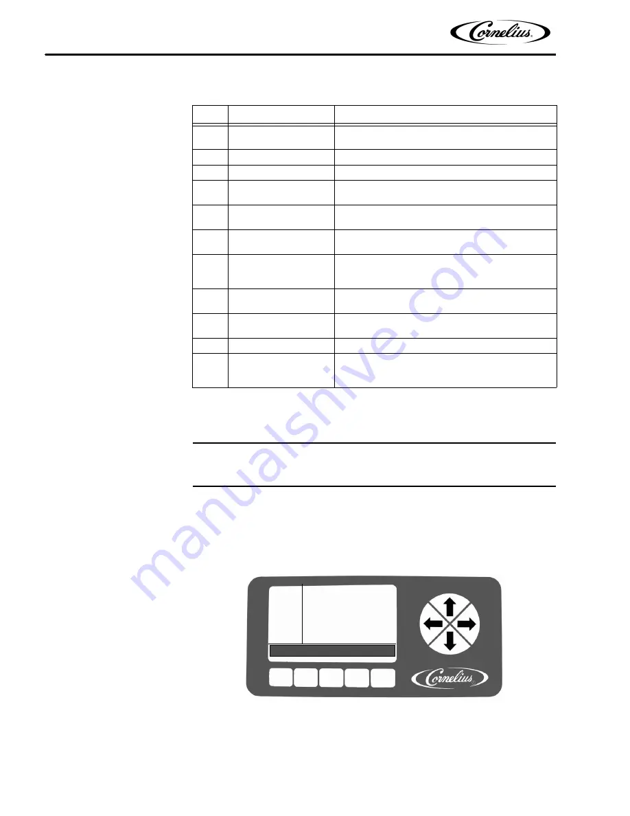
The Events Setup menu, shown in Figure 22, allows the user to set sleep periods 
for the unit and to lock out the defrost cycle during peak busy times. Sleep periods 
and defrost lockouts may be programmed for any day of the week or for all days of 
the week, depending on business requirements. Button functions are described in 

Table 15.

Figure 22. Event Setup Screen

Table 14

Step

Action

Procedure

1

Set daylight savings 
time

Press DST button at the bottom of display to open 
daylight savings time display, shown in Figure 21.

2

Select DST

Use the up and down arrows to select DST.

3

Set DST on

Use the + button to turn on daylight savings time.

4

Select SPRING 
MONTH

Use up and down arrows to select SPRING 
MONTH.

5

Set SPRING MONTH

Use the + or - buttons at the bottom of the display 
to set the correct month.

6

Select SPRING 
WEEK

Use up and down arrows to select SPRING WEEK.

7

Set SPRING WEEK

Use the + or - buttons at the bottom of the display 
to set the correct week. The choices are 1, 2, 3 or 
L.

8

Select FALL MONTH

Use the up and down arrows to select FALL 
MONTH.

9

Set FALL MONTH

Use the + or - buttons at the bottom of the display 
to set the correct month.

10

Select FALL WEEK

Use up and down arrows to select FALL WEEK.

11

Set FALL WEEK

Use the + or - buttons at the bottom of the display 
to set the correct week. The choices are 1, 2, 3 or 
L.

EVENT
SETUP

12:51P
MAR


04

DAY


SUN

SLEEP


10

:

00


PM

BACK


CLEAR

       ‐            

+

WAKEUP


08:00


AM

DEFROST


LOCK


1:


05:15


PM

DEFROST


LOCK


2:


09:30


AM

DEFROST


LOCK


3:

 ‐‐‐‐‐‐‐‐‐‐‐‐

Summary of Contents for VIPER 2 FLAVOR

Page 1: ... 3 FLAVOR VIPER 4 FLAVOR Service Manual Release Date October 28 2008 Publication Number 621260373SER Revision Date May 14 2012 Revision H Visit the IMI Cornelius web site at www cornelius com for all your Literature needs ...

Page 2: ...ervice required by or loss or damage resulting from any of the following occurrences including but not limited to 1 other than normal and proper use and normal service conditions with respect to the Product 2 improper voltage 3 inadequate wiring 4 abuse 5 accident 6 alteration 7 misuse 8 neglect 9 unauthorized repair or the failure to utilize suitably qualified and trained per sons to perform serv...

Page 3: ... Overrun as Applied to Carbonated Beverages 4 Overrun Definition 4 Overrun is a Variable 4 Specific Product Ingredients Affect Overrun 5 BRIX Affects Overrun 5 Low Dispensing Volume Affects Overrun 5 Carbonation Level in Liquid Product Affects Overrun 5 Freezing Affects Overrun 6 System Overview 7 Introduction 7 Theory of Operation 7 CO2 System 14 Water System 19 Syrup System 19 Control Panel 19 I...

Page 4: ...t 35 Setting the POS Lighting 35 Setting the Type of Syrup 35 Maintenance Menu 35 Barrel Maintenance Menu 36 Purging a Barrel 36 Filling a Barrel 37 Run the Barrel Motor 37 Rinsing a Barrel 37 Manual Diagnostic Menu 38 Totals Menu 39 BRIX Setup Menu 40 Motor Setup Menu 42 Calibrating a Motor 44 System Menu 44 Security 45 Pressure Sensors 46 Operation 47 Maintaining Product Quality 47 Dispensed Pro...

Page 5: ...ling a New Seal 62 Motor Seal Leak Test 63 Barrel Motor Replacement 64 Motor Run Capacitor Replacement 64 Water Pump Replacement 65 CO2 Shutoff Solenoid Replacement 66 Syrup and Water Shutoff Solenoid Replacement 67 CO2 Regulator Replacement 68 Condenser Fan Motor Replacement 69 Compressor Replacement 70 Hot Gas Solenoid Replacement 71 Liquid Line Solenoid Replacement 72 Syrup Pressure Switch Repl...

Page 6: ...the technician in maintaining and servicing the Viper system The Viper system is simple in design and has built in features and diagnostic controls to help the service technician quickly and accurately service the machine The unit consists of multiple freeze barrels that each contain an internal beater driven by a rear mounted electric motor a refrigeration system timer controlled automatic hot ga...

Page 7: ...erious injury death or equipment damage CAUTION Indicates a potentially hazardous situation which if not avoided MAY result in minor or moderate injury or equipment damage SAFETY TIPS Carefullyreadandfollow allsafety messages inthismanualandsafety signs onthe unit Keepsafety signsingoodconditionandreplacemissingordamageditems Learnhowtooperatetheunitandhowto usethecontrols properly Do notletanyone...

Page 8: ...t in serious injury death or equipment damage CAUTION Always be sure to keep area around the unit clean and free of clutter Failure to keep this area clean may result in injury or equipment damage SHIPPING AND STORAGE CAUTION Before shipping storing or relocating the unit the unit must be sanitized and all sanitizing solution must be drained from the system A freezing ambient environment will caus...

Page 9: ...ese carts are also designed with movable wheels that act as outriggers to provice stability to the unit when it is being moved WARNING The above listed mounting bolts must be installed and the wheels extended and locked in the outboard position prior to moving the unit Failure to comply could result in serious injury death or equipment damage DISPENSED PRODUCT CONDITIONS Overrun as Applied to Carb...

Page 10: ... products with lower BRIX freezing takes place at higher termperatures than for high BRIX products Thus BRIX affects overrun because the amount of sugar in a drink has a direct bearing on the product s freezing characteristics Low Dispensing Volume Affects Overrun When a unit sits idle fo a period of time with no drinks being dispensed CO2 gas in the system takes a set When the first few drinks ar...

Page 11: ...lius Inc Freezing Affects Overrun Freezing causes approximately a 5 7 percent expansion in dispensed frozen carbonated drinks The degree of freezing is limited because the finished drink is intended to be sipped through a straw This is not possible if the product is too solid ...

Page 12: ...a transparent faceplate with an integral relief valve and a removable self closing dispensing valve mounted on the front A removable drip tray with cup rest is located directly below the dispensing valves A programmable control system with a control panel that controls operational and diagnostic functions and settings is located behind the merchandiser THEORY OF OPERATION The refrigeration system ...

Page 13: ...Viper Service Manual Publication Number 621260373SER 8 2008 2012 IMI Cornelius Inc Figure 1 Viper System 2 Barrel Refrigeration Schematic ...

Page 14: ...Viper Service Manual 2008 2012 IMI Cornelius Inc 9 Publication Number 621260373SER Figure 2 Viper System 3 Barrel Refrigeration Schematic ...

Page 15: ...Viper Service Manual Publication Number 621260373SER 10 2008 2012 IMI Cornelius Inc Figure 3 Viper System 4 Barrel Refrigeration Schematic ...

Page 16: ...Viper Service Manual 2008 2012 IMI Cornelius Inc 11 Publication Number 621260373SER Figure 4 Viper 2 Barrel Wiring Diagram ...

Page 17: ...Viper Service Manual Publication Number 621260373SER 12 2008 2012 IMI Cornelius Inc Figure 5 Viper 3 Barrel Wiring Diagram ...

Page 18: ...Viper Service Manual 2008 2012 IMI Cornelius Inc 13 Publication Number 621260373SER Figure 6 Viper 4 Barrel Wiring Diagram ...

Page 19: ...s shown in Figure 7 and Figure 8 The CO2 system also supplies CO2 to the water boost pump the expansion tank regulator and the secondary CO2 tank regulators CO2 enters the expansion tank regulator and is reduced to approximately 30 psig to feed holding pressure on the expansion tank This provides a force to work against the barrel pressure when the product freezes and expands CO2 also enters the s...

Page 20: ... level of citric acids etc will impact settings These settings are to provide initial adjustments to achieve product overruns in the 80 120 range NOTE For citric syrups adjust the CO2 pressures down by 2 4 PSIG from the above to compensate for the lower CO2 adsorption Table 1 Syrup Type Syrup Type Set Viscosity Pressure Expansion FCB Syrup w Foaming Agent FCB 4 34 36 PSIG 30 FCB Syrup w o Foaming ...

Page 21: ...Viper Service Manual Publication Number 621260373SER 16 2008 2012 IMI Cornelius Inc Figure 9 2 Barrel System Schematic ...

Page 22: ...Viper Service Manual 2008 2012 IMI Cornelius Inc 17 Publication Number 621260373SER Figure 10 3 Barrel System Schematic ...

Page 23: ...Viper Service Manual Publication Number 621260373SER 18 2008 2012 IMI Cornelius Inc Figure 11 4 Barrel System Schematic ...

Page 24: ...onents of the machine Temperatures and pressures are monitored along with pumps valves and the refrigeration system They are managed by the control system to provide a consistently high quality product with optimal efficiency The control system is set up by the service provider to perform the tasks necessary to keep the Viper unit operating correctly In addition to controlling the unit the control...

Page 25: ...s that are taken to modify the functioning of the machine Figure 12 Control System Display Control Panel Buttons The second area are the buttons and arrows located across the bottom and on the right side of the control panel There are up to five buttons and four directional arrows that may be used on a screen to activate and control various the functions of the system Each button that is active fo...

Page 26: ...Viper Service Manual 2008 2012 IMI Cornelius Inc 21 Publication Number 621260373SER Figure 13 Software Structure ...

Page 27: ...ormal operation this screen is displayed on the control panel Figure 14 Main Screen Main Menu To access the menus for the system from the Barrel Status menu press the MENU button This displays the Select menu shown in Figure 15 The Setup and Maintenance menus are accessed through the buttons shown at the bottom of the display NOTE If security is turned on the MAINT button is not displayed Table 2 ...

Page 28: ... its parameters To view the next barrel press the Down arrow on the right side of the display Continue pressing the Down arrow to view the data on all barrels in the system Refer to Table 4 for button functions Figure 16 Unit Data Screen Table 3 Button Description BACK Returns the display to the Barrel Status menu MAIN Highlighted to indicate current menu SETUP Opens the Setup menu MAINT Displays ...

Page 29: ...l including Outlet Temperature Viscosity if Refrigeration is On or Off Average Ounces of product dispensed per hour for the last three hours and Defrost Lock Time until next defrost UNIT Displays the real time input voltage and frequency being supplied to the unit and the low high or both refrigeration pressures for the unit depending on the settings of the compressor sensors in the Unit Data scre...

Page 30: ...P HI PRESS System This error is generated if the low side pressure is greater than 55 psi for greater than 30 sec Only checked when barrels are in freeze mode and compressor is running more than two min utes BRL TEMP OUT Barrel Indicates thermistor reading is at min or max value for 30 sec without changing MOTOR STALL Barrel Motor stalled A two minute defrost and two retries are allowed then the m...

Page 31: ... for more than one second Error is cleared 10 sec after restoral SYRUP OUT Barrel Syrup pressure is below required operating pressure This error occurs when the syrup sensor reports no or low syrup pressure for more than one second Error is cleared 10 sec after restoral CLOCK System The real time system clock is not functioning MTR CTL EEPROM System Motor control EEPROM is bad or missing Table 7 B...

Page 32: ...ight side of the control panel to highlight the choices on the display When the desired option is highlighted press the GO button to access that menu Figure 19 Setup Screen Clock Setup Menu Select the CLOCK SETUP menu from the Select menu shown in Figure 19 This displays the Clock Setup menu shown in Figure 20 Button functions are described in Table 10 Table 9 Button Description BACK Returns the d...

Page 33: ...field Increments the highlighted field CLOCK SETUP 12 51P MAR 04 TIME 11 00 AM DATE 01 01 00 BACK CLOCK DST Table 11 Step Action Procedure 1 Set clock time Use up and down arrows on the right side of the control panel to highlight TIME display on screen 2 Select hour field Use the left and right arrows to select hour field 3 Set correct hour Use the or buttons at the bottom of the display to set t...

Page 34: ...isplay on screen 2 Select month field Use the left and right arrows to select month field 3 Set correct month Use the or buttons at the bottom of the display to set the correct month 4 Select day field Use the left and right arrows to select day field 5 Set correct day Use the or buttons at the bottom of the display to set the correct day 6 Select year field Use the left and right arrows to select...

Page 35: ... in Figure 21 2 Select DST Use the up and down arrows to select DST 3 Set DST on Use the button to turn on daylight savings time 4 Select SPRING MONTH Use up and down arrows to select SPRING MONTH 5 Set SPRING MONTH Use the or buttons at the bottom of the display to set the correct month 6 Select SPRING WEEK Use up and down arrows to select SPRING WEEK 7 Set SPRING WEEK Use the or buttons at the b...

Page 36: ...e sleep cycle ends If a barrel is running when the sleep cycle starts the barrel starts back up when the sleep cycle ends Wakeup should be scheduled for approximately one hour before product is required NOTE Setting the sleep time after midnight requires you to set it during the next day i e Saturday night at 1am must be set as 1am on Sunday etc If this type of setting is required you cannot set a...

Page 37: ... minutes 15 min increments 7 Select AM PM field If the 12 hour clock option is selected use the left and right arrows to select the AM PM field Then press the or buttons to change between AM and PM 8 Select DAY for Wakeup Repeat Steps 2 and 3 as needed 9 Select WAKEUP Use the up and down arrows to highlight WAKEUP and repeat Steps 5 through 7 to set the WAKEUP times Table 16 Step Action Procedure ...

Page 38: ... viscosity setting perform Steps 1 through 4 in Table 18 and then press the ALL button at the bottom of the display while highlighting the viscosity setting you desire for all the barrels When the viscosity settings are complete press the BACK button to save the settings and return to the Select menu shown in Figure 19 12 Select DEFROST LOCK 3 Repeat Steps 2 through 10 for the DEFROST LOCK 3 time ...

Page 39: ...wn in Figure 19 Setting the Temperature Format The temperature format displayed by the unit may be set to either Centigrade or Farenheit Press the F button to display readings in Farenheit and press the C button to display readings in Centigrade Setting the Date Format The date format can be displayed in either United States or European format To display U S date format press the USA button This d...

Page 40: ...cted by highlighting the desired barrel and pressing the appropriate button FCB FCB L FUB or FUB L FCB is for Frozen Carbonated Beverage FCB L is for Frozen Carbonated Beverages Light diet FUB is for Frozen Uncarbonated Beverages and FUB L is for Frozen Uncarbonated Beverages Light diet Each of these settings provides the proper viscosity and temperature settings for the type of syrup being used M...

Page 41: ...l Maintenance Screen Purging a Barrel NOTE When the PURGE button is pressed it changes to a STOP button BARREL MAINT 12 51P MAR 04 1 PURGE 2 OFF BACK PURGE FILL SPIN Table 20 Step Action Procedure 1 Purge a barrel From the Select menu Figure 25 open the Barrel Maintenance menu shown in Figure 26 2 Select the barrel Use the Up and Down arrows to highlight the desired barrel 3 Select Purge function ...

Page 42: ... bleed CO2 from the barrel 5 Complete the proce dure Press the STOP button at the bottom of the display to stop the fill Press the BACK button to return to the Select menu Table 22 Step Action Procedure 1 Run a barrel From the Setup menu Figure 25 open the Barrel Maintenance menu shown in Figure 26 2 Select the barrel Use the Up and Down arrows to highlight the desired barrel 3 Select Run function...

Page 43: ...oftware is designed to turn on the hot gas solenoid for a barrel to prevent damage from occurring 5 Override Water Sole noid Press the manual bypass on the water solenoid and fill the barrel with plain water Use the relief valve on the faceplate of the barrel to relieve pres sure and completely fill the barrel 6 Run the barrel motor Use the procedure in Table 22 to rinse the barrel 7 Complete the ...

Page 44: ...next press the Right or Left arrow keys This highlights the first entry of the second barrel etc Figure 28 Totals Screen LLS VALVE 1 This selection opens and closes the Liquid Line solenoid and valve for barrel 1 BRL MOTOR 1 This selection turns the barrel 1 motor on and off Table 24 Display Description Table 25 Display Value Description POWER ON HHHHH MM Shows how long the machine has been powere...

Page 45: ...tatus of barrels Make sure the status of all barrels is OFF on the control display 2 Remove drip tray access panel Remove the drip tray loosen the two screws holding the access panel and remove it Figure 30 3 Set product supply valve Turn product supply valve to the 180 degree BRIX position for the barrel you are testing See Figure 31 4 Access BRIX menu Press MENU Then press the SETUP button 5 Set...

Page 46: ...r range adjust the syrup water mixture by opening or closing the syrup valve shown in Figure 32 and then retest 13 Clear hose When BRIX measurement is complete press the valve on the bottom of the appropriate water solenoid to flush out the hose before closing the valve at the end of the hose 14 Set product supply valve Turn product supply valve back to the BAR REL position for the barrel you test...

Page 47: ...d unless a barrel motor or barrel components are replaced adjusted or removed and reinstalled This menu allows you to select different motor types for each barrel in the unit and run Product Supply Valve Barrel 1 Product Supply Valve Barrel 2 Valves shown in BARREL position w Splash Panel Removed Flow Controls Barrel 2 Flow Controls Barrel 1 Syrup Flow Control Water Flow Control Do Not Adjust Manu...

Page 48: ...nsure that the motor type matches the settings listed in Table 27 based on model NOTE If the Motor Type shown is DEFAULT it indicates that the EEPROM is not installed or is faulty Figure 33 Motor Setup Screen Table 27 Model Motor Type All 60 Hz 1 All 50 Hz 2 Table 28 Button Description BACK Returns the display to the Select menu CAL Verifies the motor settings of a new motor Decrements the highlig...

Page 49: ...r of items in the system generates errors or turns off some of the equipment present in the system When the individual fields are highlighted the display buttons change Refer to Table 32 for a listing of the button functions for the various field selections Table 30 Step Action Procedure 1 Re assemble barrel It is VERY IMPROTANT that calibration be per formed when the product in the barrel is in a...

Page 50: ...or when the user goes back to the Main menu security is re activated and the Maintenance menu is not accessable To disable security access the System menu highlight Security and press the OFF button Table 31 Display Description OF BARRELS This selection shows the number of barrels in the system and allows the user to change the quantity OF COMPRESSORS This selection shows the number of compressors...

Page 51: ...ossible to install sensors in the field but it is not recommended because system refrigerant charge may be lost The low side pressure sensor is used to monitor compressor reversal If it is not installed on the unit the unit may not operate properly Figure 35 System Screen When the pressure sensors selection is highlighted pressing the NONE button removes the pressure readings from the Unit Data sc...

Page 52: ...d uct to meet peak draw demands Where low product throughput is experienced there is the potential for product quality to diminish The information shown in Table 33 outlines the minimum throughput per barrel that must be dispensed on a 24 hour basis NOTE Cornelius recommends that in conditions where the FCB machine is operational and the minimum throughput as described in Table 33 is not met on a ...

Page 53: ...urn the unit to nor mal operation Cornelius recommends programming the wakeup time for approxi mately 20 minutes before the product is needed This is the time recommended if the ambient temperature is at 75 F The times will vary depending on the ambient tem perature a higher ambient temperature requires more time for the product to cool Viscosity Setting The control system includes a function to s...

Page 54: ...rator s Manual P N 621260373OPS for details on operation of the Viper unit Table 34 Step Action Procedure 1 Open the merchandiser Open the merchandiser and expose the control panel 2 Turn on the barrels Turn all barrels on by pressing the buttons labeled ON to start the normal refrigeration process 3 Close the merchandiser Close the merchandiser In approximately 20 minutes product is ready to serv...

Page 55: ...FORM TO NATIONAL AND LOCAL CODES Table 33 Preventative Maintenance Summary Maintenance Procedure Frequency of Maintenance Clean Air Filter Monthly or more often as necessary See Table 34 Check BRIX Every six months or when changing syrup types See BRIX Setup Menu on page 40 Seal Change Every six months Clean Condenser Coil Every six months or as necessary Sanitize Unit Every six months or when cha...

Page 56: ... Filter The air filter should be cleaned at least once a month more often in harsh envi ronments Perform the procedure in Table 34 to clean the air cleaner Figure 37 Air Filter Location Table 34 Step Action 1 Open the merchandiser 2 Remove the filter shown in Figure 37 by grasping the two tabs and sliding it straight out the front of the unit 3 Wash the filter with clean water Shake out the excess...

Page 57: ... Action 1 See Purging a Barrel on page 36 2 When purging is complete remove power from the unit 3 Remove the four 4 3 4 in nuts from the faceplate and slowly remove the faceplate from the unit 4 Slowly pull the blade assembly out of the barrel 5 Rinse and inspect the blade assembly for signs of wear 6 If there is significant wear on the blades Reverse or replace them depending on the wear pattern ...

Page 58: ...ensing valve on the unit Figure 38 Self Closing Dispensing Valve Table 36 Step Action 1 Open the merchandiser and select OFF for the barrel to be cleaned 2 Remove the quick disconnect from the BIB container 3 Fill a suitable pail or bucket with soap solution 4 Submerge the disconnect in the soap solution and then clean it using a nylon bristle brush Do not use a wire brush Rinse with clean water a...

Page 59: ... to remove excess syrup and lubri cant especially from caged o ring and dispensing valve Use a brush provided with the unit to clean the faceplate relief valve passages 14 Submerge all the parts in a 4 percent solution of approved sanitizing agent for the amount of time recommended by the sanitizer manufacturer 15 Remove the parts from the sanitizing solution and place them on clean paper towels 1...

Page 60: ...ep Action 1 From the Barrel Status menu press the DFRST button 2 When the barrel is defrosted go to the Maintenance menu If the security fea ture is active access the Maintenance menu by by pressing and holding the far left and right buttons simultaneously for approximately five seconds 3 Remove the splash panel See BRIX Setup Menu on page 40 4 Turn the Product BRIX valve 90 degrees clockwise to s...

Page 61: ...ure in the barrel drops from the Barrel Maintenance menu press the PURGE button to re pressurize the barrel with CO2 As the wash water level lowers in the bar rel partially close the valve to avoid spurting 10 Perform rear barrel seal replacement See Barrel Motor Seal Replacement on page 61 11 Perform inspection and replacement of scraper blades See Inspecting and Replacing Scraper Blades on page ...

Page 62: ...n 1 Turn the Product BRIX valve to the Product position 2 Manually open the manual water flow valve to start filling the barrel with wash water At the same time open the faceplate relief valve until water comes out 3 From the Barrel Status menu press the SPIN button while highlighting the appropriate barrel This starts the scraper blade Allow the blade to operate for fifteen seconds then turn barr...

Page 63: ... to Figure 39 for water filter location Figure 39 Water Filter Location Table 42 Step Procedure 1 Disconnect power from the unit 2 Turn off and disconnect the water supply to the unit 3 Remove the rear cover of the unit 4 Disassemble the water filter Use two wrenches if necessary 5 Remove the filter and rinse it under running water to remove any debris 6 Reassembe the filter 7 Connect and turn on ...

Page 64: ...ion 1 Purge the barrel See Purging a Barrel on page 36 2 When purging is complete disconnect power from the unit 3 Open the relief valve on the front of the barrel to ensure that pressure is released CAUTION Barrel pressure MUST be relieved before removing the faceplate 4 Remove the four 4 3 4 in nuts from the faceplate and slowly remove the face plate from the unit 5 Carefully pull the blade asse...

Page 65: ...er portion of the seal This could cause the seal to rotate in the bore and leak 6 Carefully slide the seal over the motor shaft and press it firmly until is fully seated against the spacer and the seal cannot be pushed any further 7 Run your finger around the perimeter of the seal to insure it is flush against the back of the barrel 8 Reinstall the blade assembly Rotate the assembly while insertin...

Page 66: ...he 3 way Product Supply valve behind the splash panel see Figure 31 to the Off horizontal position 2 From the Maintenance menu press the FILL button for the barrel This pres surizes the barrel with CO2 3 Observe the water and syrup fill solenoids 4 If there are NO seal leaks these solenoids cycle off within a minute and remain off 5 If the solenoids cycle off and remain off the barrel seal is not ...

Page 67: ... rear of the unit between the barrel motors To replace a run capacitor perform the proce dure in Table 47 Table 46 Step Action 1 Perform the procedure in Steps 1 through 8 of Table 43 2 Disconnect the motor from the circuit by unplugging the connector 3 Remove the motor by removing the four 4 bolts holding the motor to the bar rel assembly 4 Install the replacement motor and connect the connector ...

Page 68: ...re 45 Rear View of Water Pump Table 47 Step Action 1 Disconnect power from the unit 2 Remove the rear cover 3 Disconnect the spade clips from the defective capacitor 4 Remove the mounting screw from the base of the capacitor 5 Replace the capacitor 6 Reverse the procedure to install the new capacitor 7 Reconnect power to the unit 8 Refill the barrel with product See Filling a Barrel on page 37 9 W...

Page 69: ...isalign the CO2 metering orfice To replace one of these solenoids perform the procedure in Table 49 Figure 46 Side View of CO2 Shutoff Solenoid 2 Barrel Unit Table 48 Step Action 1 Disconnect power from the unit 2 Remove the rear cover and the side panels 3 Disconnect the CO2 supply from the unit 4 Remove and drain the water supply from the unit 5 Disconnect the quick disconnect input and output w...

Page 70: ...ove the rear cover and side panels 4 Carefully remove the tubing from the right angle fitting at the rear of the valve Be sure not to damage the CO2 metering orfice located above the fitting Fig ure 46 5 Remove the tubing from the front of the valve 6 Remove the two 2 locknuts mounting the valve and solenoid to the base 7 Remove the two 2 mounting screws from the bottom of the mounting bracket 8 R...

Page 71: ... the rear cover and side panels 4 Remove the water and syrup lines from the input to the valves 5 Remove the Wye tube from the output top of the valves by loosening the nuts between the Wye and the check valves 6 Remove the two 2 locknuts from the base of the assembly and remove it from the unit 7 Remove the check valve from the valve being replaced 8 Install the check valve on the new valve and s...

Page 72: ...e panel 3 Turn off the CO2 source and then turn the Product valve 90 degrees to the off position 4 Relieve pressure in the barrel by opening the relief valve on the faceplate of both barrels 5 Disconnect the three 3 supply lines at the rear of the regulators using a small wrench 6 Remove the two lock nuts from the mounting bracket in back of the regulators 7 Remove the pressure switch wires from t...

Page 73: ... condenser 4 Lift the fan and shroud off the unit 5 Remove the four screws and washers securing the fan to the shroud 6 Replace the fan 7 Reverse the procedure to install the new fan 8 Reconnect power to the unit Locking Nuts Locking Nuts Table 53 Step Action 1 Disconnect power to the unit 2 Remove the rear cover and side panels 3 Label and disconnect all wires from the compressor 4 Remove the fou...

Page 74: ...r 11 Evacuate the system and recharge it according to the Cornelius nameplate on the unit 12 Replace the side panels and rear cover 13 Reconnect power to the unit and test the unit Table 53 Step Action Table 54 Step Action 1 Disconnect power from the unit 2 Remove the side panels 3 Reclaim refrigerant from the system 4 Carefully remove the insulation and remove the hot gas valve and solenoid 5 Rep...

Page 75: ...eft and right sides of the unit near the front There is one switch for each barrel in the system Figure 52 shows the syrup pressure switch on the left side of the unit To replace the syrup pressure switch perform the procedure in Table 56 Table 55 Step Action 1 Disconnect power from the unit 2 Remove the side panels 3 Reclaim refrigerant from the system 4 Carefully unwrap the foam insulation from ...

Page 76: ...f the unit when viewed from the rear To replace the water pressure switch perform the procedure in Table 57 Table 56 Step Action 1 Disconnect power to the unit 2 Remove the appropriate side panel 3 Turn off the syrup supply to the unit 4 Drain the syrup from the system 5 Disconnect the wires on the pressure switch 6 Remove the switch using two wrenches 7 Replace the switch with a new unit 8 Revers...

Page 77: ...t power from the unit 2 Remove the side panel from the unit 3 Turn off the water supply to the unit 4 Drain the water from the system 5 Disconnect the wires from the switch 6 Remove the switch using two wrenches 7 Replace the switch with a new unit 8 Reverse the procedure to install the new switch 9 Restore the water supply and check for leaks 10 Check to ensure that the new switch is working prop...

Page 78: ...ox Backward Forward Compatibility with Older Software Versions With version 3 0 software release several of the boards used to control the equipment will not be backward compatible with boards containing version 2 x of the software Please refer to the table below for compatibility Table 59 Step Action 1 Disconnect power from the unit 2 Connect a static strap to your wrist and any convenient chassi...

Page 79: ...by an alpha suffix designating the language type The motor control boards and the main status board will still operate with either version 2 x or 3 x software of UI and IO board When ordering replacement service parts for any unit check the software ver sion of the UI and IO boards and be sure to order the correct board as listed in Table 60 MOTOR BOARD REPLACEMENT When replacing or testing electr...

Page 80: ...621260373SER Figure 56 View of Motor Board in E Box 4 Squeeze each of the mounting studs at the corners of the board while care fully lifting the board 5 Replace the board with a new board 6 Reverse the procedure to install the new board Table 61 Step Action Mounting Studs ...

Page 81: ...sleep programming C Check sleep programming Barrel status OFF A Not activated B Error has shut off motors C Unit in Diagnostics D Defective touch switch A Turn to ON DFRST or SPIN B Correct error turn to ON DFRST or SPIN C Exit diagnostics turn to ON DFRST or SPIN D Replace Low High voltage ERROR A Line Voltage out of SPEC spec is 205 255 VAC for 60 Hz and 196 265 VAC for 50 Hz B Error range 180 2...

Page 82: ...ter C Condenser fan motor blade defec tive D Hot gas valve leaking or open E Defective compressor A Repair leak and weigh in new charge B Clean or repair C Repair or replace D Replace E Repair or replace Restricted Air Flow A Dirty filter B Dirty condenser C Damaged fins D Not enough clearance around unit A Clean filter B Clean condenser C Repair replace if necessary D Ensure proper spacing around...

Page 83: ...Viper Service Manual 2008 2012 IMI Cornelius Inc 74 Publication Number 621260373SER ...

Page 84: ......

Page 85: ...IMI Cornelius Inc www cornelius com ...

Reviews: