Conductix-Wampfler MultiLine 0835 Mounting Instruction Download Page 31

Mounting Instruction 


Conductor rail system 

MultiLine 0835 


MAL0835-0001c-EN 
www.conductix.com 

translated document 

page 31 of 81 


Avoid mechanical vibrations 


Storage temperature: -25 °C to max. 55 °C 


Relative humidity: max. 85% 


When storing for more than 3 months, check the general condition of all parts and the packaging at regular intervals. If 
necessary, add or replace the preservative material 


CAUTION!


If stored within this temperature range, stacking the conductor rails on top of each other can 
cause the plastic insulation profiles to deform! 


Taking the conductor rails out of their packaging 

5.3


Removing the packaging 

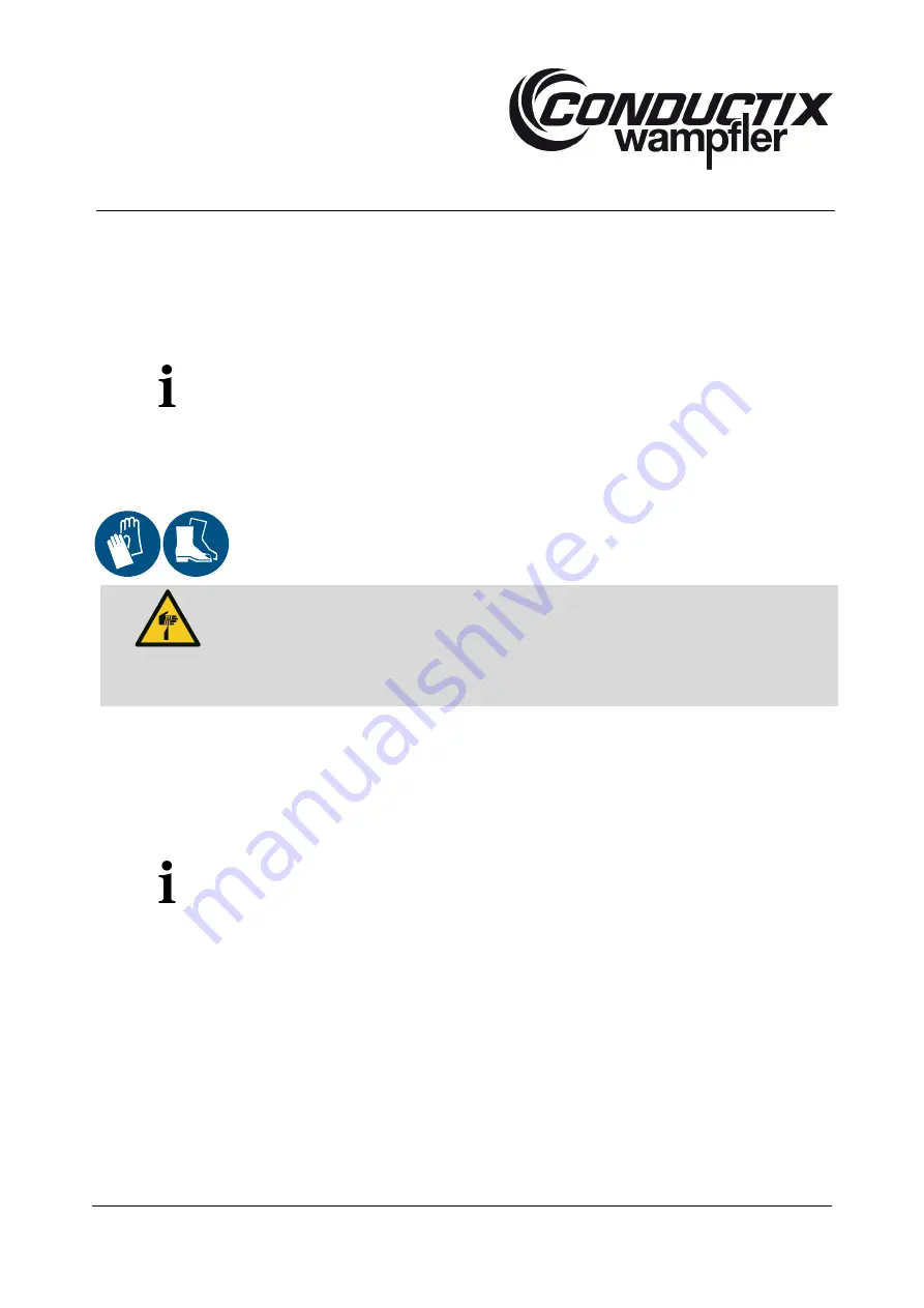
Required protective equipment: 


CAUTION! 

Risk of injury from punctures and cuts!


The packaging material can contain sharp objects such as nails and wood splinters that 

can cause injury to limbs. 


Wear protective gloves 


Wear safety shoes 


The packaging is designed to protect the individual components from transport damage, corrosion and other damage until 
installation. As a result, do not destroy the packaging and remove it only shortly before installation. 
 
Only environmentally friendly materials have been used for packaging. Dispose of packaging material according to valid legal 
regulations and local guidelines. 


CAUTION!


Environmental damage due to improper disposal!


Packaging material is a valuable resource and can be reused, reprocessed or recycled in  

many cases. 


Dispose of packaging materials in an environmentally appropriate manner 


Comply with locally applicable disposal guidelines; if necessary, commission a specialist to dispose 

of the packing 

Summary of Contents for MultiLine 0835

Page 1: ...Mounting Instruction Conductor rail system MultiLine 0835 MAL0835 0001c EN www conductix com translated document page 1 of 81...

Page 2: ...zed personnel 8 2 2 3 Training 9 2 3 Personal protective equipment 9 2 4 Intended use 10 2 4 1 Improper use 10 2 5 Protective measures to be taken by the operator user 11 2 6 5 safety rules for workin...

Page 3: ...rt 29 5 1 2 Transporting the packed parts 30 5 1 3 Transport inspection 30 5 2 Storing the packed parts 30 5 3 Removing the packaging 31 6 Installation 32 6 1 Safety 32 6 1 1 Personnel 32 6 1 2 Safety...

Page 4: ...ng operation 62 9 Servicing and maintenance 63 9 1 Safety 63 9 2 Tools and materials 66 9 3 Cleaning 66 9 4 Servicing schedule 66 10 Repairing faults 70 10 1 Fault remedy table 72 11 Dismantling and d...

Page 5: ...of the art and our long years of experience and knowledge The manufacturer is in no way liable for damage resulting from Failure to comply with this installation and mounting instruction Improper use...

Page 6: ...parts can be ordered from your contracted dealer or directly from the manufacturer See section 14 for the contact details for ordering spare parts 1 5 Material defects The regulations about material d...

Page 7: ...y DANGER indicates an immediate hazard that if not avoided may result in death or serious injury DANGER indicates an immediate hazard due to electrical current which if not avoided may result in death...

Page 8: ...ning for example as electricians master electricians electrical engineers or electrical technicians Personnel are also considered qualified who have been employed correspondingly for several years hav...

Page 9: ...d no protruding parts Protective footwear Used to protect feet from heavy falling parts and slipping on slippery floors To be worn for special tasks When carrying out certain tasks personnel must wear...

Page 10: ...speed is 300 m min The conductor rail must only be fitted horizontally CAUTION To fit the conductor rail vertically there are a number of extra points that need to be taken into consideration and doi...

Page 11: ...oncerning workplace safety In addition to the safety guidelines in this installation and operating manual the safety accident protection and environmental protection regulations applicable to the plac...

Page 12: ...2009 10 EN 50110 1 2004 11 must always be followed before starting any work 1 Disconnect system from the power supply at the main switch 2 Secure the main switch against being switched back on 3 Check...

Page 13: ...and secure it against being switched back on For the 5 safety rules see section 2 6 CAUTION Before switching the system on Every time before the device or system is started measure the insulation resi...

Page 14: ...See section 12 3 2 7 2 Mechanical hazards and sources of danger Required protective equipment DANGER Risk of injury through crushing and impacts There is a risk of crushing skin and limbs from Curren...

Page 15: ...lide out of the insulation profiles if they are not held roughly vertical during transport This can cause serious injury and even death if they fall from a great height and hit somebody with their fro...

Page 16: ...also strongly frequented facilities personnel must be protected through effective measures against dust Personal protective equipment must be worn during all works on the conductor rail system during...

Page 17: ...a conductive material Secure the electric system according to regulations Install the conductor rail as described in the installation manual Take environmental conditions into account perform regular...

Page 18: ...on the conductor rail system during which collected dust is disturbed The following personal protective equipment must be worn during cleaning operations Safety goggles Dust mask class FFP3 Gloves Dis...

Page 19: ...against entry Consult qualified personnel when analysing the fault Conductix Wampfler must be informed immediately in the event malfunctions can cause personal injury or damage to property Conductix W...

Page 20: ...5 2 5 mm or 4 6 mm Conductor material Copper or steel Protection class IP 2X 3 2 Mechanical Max travel speed 300 m min Direction of travel Back and forth reversing Gap between pins 14 mm 3 2 1 Length...

Page 21: ...em lengths when using standard components LSTD see section 13 1 3 2 2 Installation orientation WARNING Do not fit the conductor rails vertically Fit conductor rails horizontally and level see section...

Page 22: ...ibility for the conductor rail s correct functioning if these tolerances are not observed In such a case Conductix Wampfler does also not accept any liability for any problems that may arise if the co...

Page 23: ...ng chemical substances or gases that can potentially permanently damage the conductor rail s materials corrosion or drastically impact on the insulation In ambient air that contains solvent vapours or...

Page 24: ...are securely connected The power feed at the top end of the conductor rail is used to supply the rail with electrical energy that the shuttle or a different kind of mobile consumer can continuously a...

Page 25: ...1 x PE protective earth DANGER In a worst case scenario dismounting the connectors can cause a fire The connectors cannot be removed Using force to remove a connector will damage the connector and me...

Page 26: ...animation MultiLine 0835 System Overview 4 3 Accessories The following accessories are included in the scope of delivery Fig 9 Arrester 0835 Arrester 0835 The arrester is fitted to the very top end of...

Page 27: ...p bar End cap Crimp type sockets 2 5 mm2 and 6 mm2 Connector cap Hanger clamps Expanding rivet Installation block 0835 Stop 0835 4 4 Overview of the system Fig 11 Overview First section A middle secti...

Page 28: ...conductor bars and move in line with the conductor bars when they expand The insulation profiles of the conductor rail segments are 15 mm shorter than the conductor bar to compensate for the differen...

Page 29: ...the workplace DANGER Risk of injury from falling power rails when transported incorrectly When being transported on the construction site there is a risk that the power rails may slide out of the insu...

Page 30: ...ve been packed in accordance with the anticipated transport conditions Check the delivery for completeness and transport damage immediately on receipt If transport damage is externally visible proceed...

Page 31: ...es and cuts The packaging material can contain sharp objects such as nails and wood splinters that can cause injury to limbs Wear protective gloves Wear safety shoes The packaging is designed to prote...

Page 32: ...ements are tightly fastened Only use authorized lifting accessories and connection elements with sufficient load capacity Discard torn or worn ropes or straps and replace with new ones Do not attach r...

Page 33: ...ng on the conductor rail system protective footwear protective gloves and protective headgear must be worn When exchanging carbon brushes observe the separate instructions on this topic See section 12...

Page 34: ...ere injury There is also a risk of injury from shock falling or being thrown across the room as a result of an electrical shock DANGER Risk of injury from falling or being thrown across the room after...

Page 35: ...onductor rails or must make the danger area inaccessible e g by providing a cover CAUTION Take the requisite protective measures Fit a contact guard that will safely cover the sliding contact if it st...

Page 36: ...efore doing so See section 6 2 4 When using copper conductor bars use copper plated connectors When using steel conductor bars use tin coated connectors Connector caps The connector caps have to be su...

Page 37: ...onnector pins into the end of the old rail section and fit the connector cap Fit the replacement rail piece into the connector pins and make connection push rail on as far as possible and close connec...

Page 38: ...showing the possible total minimum and maximum system lengths when using standard components LSTD see section 13 1 In most cases it is not actually possible to achieve the actual length required proje...

Page 39: ...on Example 2 Projected length LP 45780 mm Length achieved using standard components LSTD 45530 to 45554 mm X LP LSTD 226 250 mm the tolerance for the clearance of the conductor bars means that the sys...

Page 40: ...he material thickness of the installation surface Diameter X of the holes for the fastening holes mm Material thickness of the installation surface mm 4 6 0 05 3 4 7 0 05 4 4 8 0 05 5 4 9 0 05 6 Drill...

Page 41: ...m The end cap base has to be aligned flush with the direction of travel Fig 20 Aligning the end cap bar Fasten the end cap base 5 with the countersunk screw M4 1 the washer 3 and lock nut 2 Tightening...

Page 42: ...CAUTION The hanger clamp clips have to point upwards Make sure that the hanger clamps are fitted in the correct positions see section Fig 22 Fit the hanger clamps take note of the correct intervals s...

Page 43: ...e power source or do not yet connect the cable that is not going to be connected to the conductor rail s power terminal Protect the power supply from being switched back on Make sure the system is dis...

Page 44: ...ctor bar is pushed in as far as the power feed terminal see Fig 28 Fig 25 Push power feed terminals with crimped connection cables onto the rail Fig 26 Correct Power feed terminals are pushed onto the...

Page 45: ...the rail with the mounted end caps into hanger clamps and end cap set Fig 30 Clip the rail with end caps into hanger clamps and end cap base 1 Hanger clamp 2 Insulation profile 3 Support profile custo...

Page 46: ...terial The connectors and rails must only be fitted if the rails are fastened to a level installation surface Do not connect them before they are fitted Follow the installation manual Wear protective...

Page 47: ...en the arrester in front of the end cap base with a screw clamp Fig 32 Fastening the arrester Insert one connector for each conductor bar and lightly push in by hand Fig 33 Insert connectors by hand D...

Page 48: ...he conductor rail up to the stop Fig 35 Connector cap pushed onto the conductor rail Clip the next conductor rail into the hanger clamp see Fig 22 Align the conductor bars to be flush with the insulat...

Page 49: ...ng a gap of approx 2 5 mm see Fig 39 Repeat the process until the rail has reached the projected length minus the two last rail segments which corresponds to a gap of approx 4 to 8 mm Check whether 1...

Page 50: ...free space at the end The conductor bar must be protruding 15 mm from the insulation profile at the other end Measure the required protruding section of rail from the end of the conductor bar mark an...

Page 51: ...lide the power feed terminals into the conductor bar of the already mounted conductor rail Slide the end caps over the power feed terminals Tighten the cylinder screw on the power feed terminals Tight...

Page 52: ...e current collectors Aligning the current collectors see Fig 45 CAUTION The current collectors must be able to move freely in order to maintain the best possible level of contact with the conductor ba...

Page 53: ...d the lane must be divided accordingly Example If an 83 m long lane is to be fitted with an end segment power feed and an additional power feed in the middle of the lane the lane has to be divided as...

Page 54: ...to the start of the 2 section CAUTION Fit section 2 in the same way as section 1 Remove the arrester with the screw clamp once the 2nd section and end section has been fitted Connect both sections wi...

Page 55: ...k end of the 2nd section Attach the connector cap at the back and clip it into the yellow insulation profile Tighten the clamping screws of the two power feeds with an Allen wrench Tightening torque 2...

Page 56: ...l system or using several power feeds will reduce the conductor rail s effective length CAUTION The conductor rail system conductor and insulation expands at different rates when it becomes warm It mu...

Page 57: ...he insulation resistance before commissioning the system This must be done in compliance with the local technical standards guidelines and legislation Always make sure that all of the assembly and ins...

Page 58: ...stallation height as per specifications see section 3 Components must be clean and in perfect working order The clearance of the rail joints 2 5 mm 1 mm on each side visual inspection Distance of the...

Page 59: ...ed electrical tests Move a loose current collector over every pole of the conductor rail system and check for freedom of motion The current collector may not stick and must slide in the rail without h...

Page 60: ...e section 8 3 The safety information in section 8 1 has to be observed to ensure the system s safety during operation 8 1 Safety 8 1 1 Personnel NOTE The system must only be operated by trained person...

Page 61: ...and similar substances can cause the conductor rails holders to fail and cause the conductor rail to fall down if they are kept near the conductor rail system Food that contains and from which aromati...

Page 62: ...sumers shuttles have to be supplied with energy The consumer travels back and forth reverses and operates automatically 8 3 Stopping the system Requirement DANGER Risk of injury from electric shock Di...

Page 63: ...tective equipment may be affected by the following Irritation of the mucous membranes Diseases of the respiratory tract Cancer At workplaces that are continuously exposed and also strongly frequented...

Page 64: ...or rail system from the power supply according to the 5 safety rules and secure it against being switched back on For the 5 safety rules see section 2 6 CAUTION Before switching the system on Always t...

Page 65: ...the conductor rail system protective footwear protective gloves and protective headgear must be worn When exchanging sliding contacts observe the separate instructions on this topic See section 12 3...

Page 66: ...ts Washing Replacing Testing Resetting Readjusting The following sections describe the servicing work required for optimal and trouble free operation The tasks specified and performed as per the maint...

Page 67: ...the mucous membranes Diseases of the respiratory tract Cancer At workplaces that are continuously exposed and also strongly frequented facilities personnel must be protected through effective measure...

Page 68: ...ame 1 Conductor surface of the conductor rails 2 Middle joint 3 Spring Check the sliding contact insulation for cracks and abrasion If the insulation is damaged and the sliding contact is visible or t...

Page 69: ...ble spring balance to the current collector arm as close as possible to the middle joint of the two current collector heads Pull the current collector head vertically away from the conductor bar with...

Page 70: ...nductor rails and the guide profile This dust is very fine and is categorized as a health risk Working a lot with the conductor rail system and or not applying the requisite level of care when handlin...

Page 71: ...a result of an electrical shock Work on the following components is dangerous Main power supply Live components Power feeds Cables Connections Conductor rail Connectors Current collector Equipment and...

Page 72: ...ads move the current collector to the correct height see Fig 45 and Fig 46 Sliding contacts are wearing too fast Sharp edges on the power terminal conductor rails connections between the conductor rai...

Page 73: ...ly used transfer points where the direction of travel is reversed Adjust the consumer s movement profile Move over the end position to push the collected abrasive dust out of the conductor bar Insulat...

Page 74: ...ANGER Risk of death by electrocution Contact with components carrying electrical power can lead to death by electrocution or severe injury There is also a risk of injury from shock falling or being th...

Page 75: ...must be protected through effective measures against dust Personal protective equipment must be worn during all works on the conductor rail system during which collected dust is disturbed The followin...

Page 76: ...11 2 1 General information on dismantling the system Once the system is no longer in use it has to be disassembled and disposed of in an environmentally friendly way Before starting disassembly Remov...

Page 77: ...nductor rails CAUTION Risk of injury when removing the connector The connector is very large compared to the insulation profile and the conductor bar and an e g saw blade could easily become trapped i...

Page 78: ...led Plastic components must be recycled Sort other components by type of material and dispose of accordingly CAUTION Environmental damage due to improper disposal Electrical waste electronic component...

Page 79: ...2 1 Conformity declaration The conformity declaration for this product can be obtained from Conductix Wampfler on request 12 2 Spare parts list The spare parts are listed in the relevant catalogues 12...

Page 80: ...8 33 522 5 33 540 5 9 37 525 0 37 545 0 10 41 527 5 41 549 5 11 45 530 0 45 554 0 12 49 532 5 49 558 5 13 53 535 0 53 563 0 14 57 537 5 57 567 5 15 61 540 0 61 572 0 16 65 542 5 65 576 5 17 69 545 0...

Page 81: ...enance and servicing 63 Maintenance plan 66 Malfunctions 18 Material defects 6 Operating conditions 23 Operator 11 Other applicable documents 79 Packaging 31 Personnel 8 Product description 24 Protect...

Reviews: