background image

4-2

   Compaq ProLiant 8500 Servers Setup and Installation Guide

Compaq Confidential – Need to Know Required

Writer:

 Rick Chew  

Project:

 Compaq ProLiant 8500 Servers Setup and Installation Guide  

Comments:


Part Number:

 323333-001  

File Name: 

e-ch4 Installing Hardware.doc  

Last Saved On: 

5/5/99 10:11 AM

Installing a Hot-Plug Power Supply

The ProLiant 8500 ships with either one or two hot-plug power supplies
depending on the model. The system power in the ProLiant 8500 Server does
not have to be shut off to replace one of the power supplies.

WARNING:

  To reduce the risk of electric shock or damage to the equipment:


Install the power supply before connecting the power cord to the power
supply.


Unplug the power cord before removing the power supply from the server.


Disconnect power from the server by unplugging all power cords from
either the electrical outlet or the server.

To replace a hot-plug power supply with the system power ON:


1.


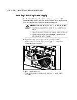
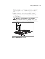
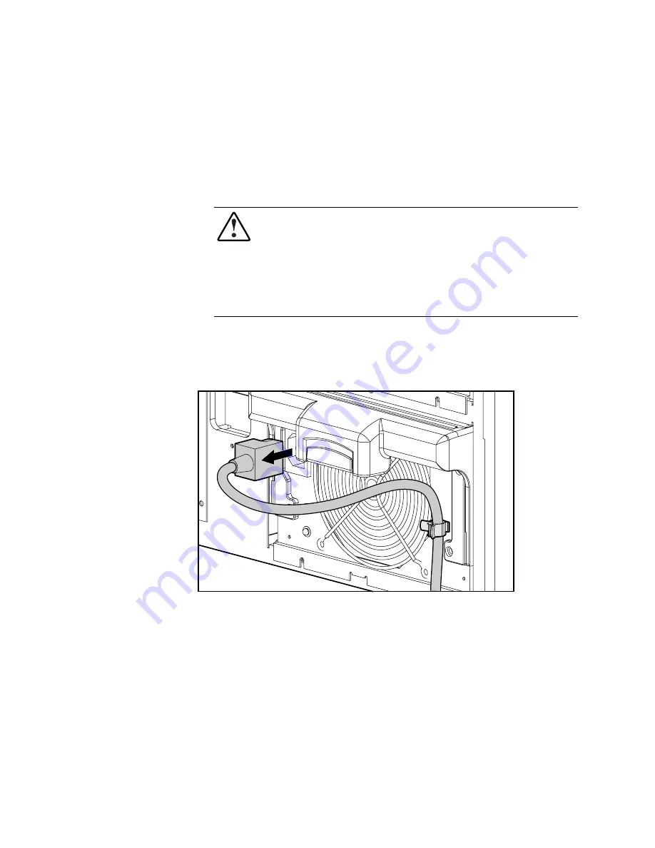
Remove the power cord from the power supply to be replaced and
release the power cord clamp.

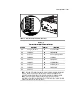
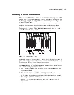
Figure 4-1.  Removing power cord


2.


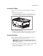
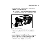
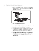
Squeeze upward on the release in the middle of the power supply
handle 

1

.

Summary of Contents for ProLiant 8500

Page 1: ...ProLiant 8500 Servers Setup and Installation Guide First Edition May 1999 Part Number 323333 001 Compaq Computer Corporation ...

Page 2: ...Compaq Computer Corporation All rights reserved Printed in the U S A The software described in this guide is furnished under a license agreement or nondisclosure agreement The software may be used or copied only in accordance with the terms of the agreement Compaq Deskpro Fastart Compaq Insight Manager Systempro Systempro LT ProLiant ROMPaq QVision SmartStart NetFlex QuickFind PaqFax ProSignia reg...

Page 3: ...500 Servers 1 1 Features 1 3 Processor and Redundant Processor Power Modules 1 3 System Memory 1 4 Cache Accelerator 1 4 Expansion Slots 1 4 PCI Hot Plug 1 4 Redundant Hot Plug Fan 1 5 Internal Hot Plug Drive Bays 1 5 Fixed Internal Media Drive Bays 1 5 Disk Controllers 1 5 Network Controller 1 6 Supported Interfaces 1 6 Video 1 6 Service Improvement Features 1 6 Power Supplies 1 7 Remote Flash Re...

Page 4: ...Space Requirements 2 3 Power Requirements 2 3 Grounding 2 4 Temperature Requirements 2 4 Airflow Requirements 2 6 Unpacking the Shipping Boxes 2 7 Removing the Shipping Brackets and Screws 2 8 Locating the Server Access Panel Labels and System Interlock Status Indicators 2 11 Rack Warnings and Precautions 2 12 Server Warnings and Precautions 2 12 Attaching the Slide Rails to the Server 2 13 Attach...

Page 5: ...he Media Module 3 11 Chapter 4 Installing Hardware Options Installing a Hot Plug Power Supply 4 2 Installing a Pentium III Xeon Processor and Processor Power Module 4 5 Installing the Cache Accelerator 4 11 SDRAM Memory 4 13 Adding or Replacing Memory 4 14 Mass Storage 4 17 SCSI Hard Drive Installation Guidelines 4 19 Installing a Hot Plug SCSI Hard Disk Drive 4 20 External Storage Devices 4 24 I ...

Page 6: ...cessing On line 5 10 SmartStart and Support Software CD 5 11 Chapter 6 Server Configuration Using Compaq SmartStart 6 1 Chapter 7 Integrated Management Log Multiple Ways of Viewing the Log 7 2 Integrated Management Display 7 2 Configuring the Integrated Management Display 7 2 Setup with the System Configuration Utility 7 2 Customizing Management Display Fields 7 4 Standard Integrated Management Di...

Page 7: ...3 Canadian Notice Avis Canadien A 3 Class A Equipment A 3 Mouse Compliance Statement A 3 European Union Notice A 4 Japanese Notice A 4 Taiwanese Notice A 4 Laser Devices A 5 Laser Safety Warnings A 5 Compliance with CDRH Regulations A 5 Compliance with International Regulations A 5 Laser Product Label A 6 Laser Information A 6 Battery Replacement Notice A 7 Appendix B Electrostatic Discharge Groun...

Page 8: ...isk of personal injury from electrical shock and hazardous energy levels only authorized service technicians should attempt to repair this equipment Improper repairs could create conditions that are hazardous IMPORTANT The installation of options and servicing of this product shall be performed by individuals who are knowledgeable of the procedures precautions and hazards associated with equipment...

Page 9: ...instructions NOTE Text set off in this manner presents commentary sidelights or interesting points of information Symbols on Equipment These icons may be located on equipment in areas where hazardous conditions may exist Any surface or area of the equipment marked with these symbols indicates the presence of electrical shock hazards Enclosed area contains no operator serviceable parts WARNING To r...

Page 10: ...e all power cords to completely disconnect power from the system Compaq Technician Notes WARNING Only authorized technicians trained by Compaq should attempt to repair this equipment All troubleshooting and repair procedures are detailed to allow only subassembly module level repair Because of the complexity of the individual boards and subassemblies no one should attempt to make repairs at the co...

Page 11: ...computer CAUTION The computer is designed to be electrically grounded To ensure proper operation plug the AC power cord into a properly grounded AC outlet only Where to Go for Additional Help In addition to this guide the following information sources are available User Documentation Compaq Service Quick Reference Guide Service Training Guides Compaq Service Advisories and Bulletins Compaq QuickFi...

Page 12: ...Reseller In the United States call 1 800 345 1518 In Canada call 1 800 263 5868 For Compaq technical support In the United States and Canada call 1 800 386 2172 For Compaq technical support phone numbers outside the United States and Canada visit the Compaq website at http www compaq com ...

Page 13: ...RAM memory Input output I O performance is further enhanced by eleven 64 bit PCI slot two of those slots operating at 66MHz a Integrated Smart Array Controller Ultra2 support and Wide Ultra2 SCSI hard drives High availability features include PCI Hot Plug slots redundant hot pluggable power supplies redundant hot pluggable fans redundant processor power modules redundant network interface controll...

Page 14: ...el and three removable modules the Processor and Memory module the Media module and the I O Module See Figures 2 1 and 2 2 for identification of these modules and other components 1 2 4 5 3 Figure 1 1 Compaq ProLiant 8500 Server front view 1 Processor and Memory module 2 Media module 3 Integrated Management Display IMD on some models 4 IDE CD ROM 5 1 44 MB Diskette Drive ...

Page 15: ...lies Features The following features are available on Compaq ProLiant 8500 models Processor and Redundant Processor Power Modules Supports up to eight Pentium III Xeon processors Thermal plate attached to the processor Supports up to eight Processor Power Modules plus one power module for processor bus termination Redundant Failover Support on some models ...

Page 16: ...ors are installed on both processor buses Expansion Slots Eleven I O expansion slots Nine 33 MHz 64 bit PCI Hot Plug slots PCI Buses 1 and 2 Two 66 MHz 64 bit PCI Hot Plug slots PCI Bus 3 PCI Hot Plug PCI Hot Plug provides the ability to remove replace upgrade and add PCI expansion boards without powering down the server Any PCI board can be placed in a PCI Hot Plug slot PCI Hot Plug device driver...

Page 17: ... are controlled by a Dual Channel Integrated Smart Array Controller See Chapter 5 SCSI Setup for a description of the integrated controller Fixed Internal Media Drive Bays Supports two non hot plug media drive bays One third height drive bay occupied by 1 44 MB diskette drive One third height drive bay occupied by IDE CD ROM drive Disk Controllers The Compaq ProLiant 8500 server is provided with a...

Page 18: ... This feature may be used with one dual port two dual port or two single port NICs NOTE Remove the terminator plug from the second RJ 45 connector when using the dual port capabilities Supported Interfaces Wide Ultra2 SCSI Very High Density Connector Interface connector Serial two connectors Video Parallel port Keyboard Mouse Video Integrated PCI Video Controller provides maximum resolution of 102...

Page 19: ...cessors Hard Drives Memory PCI Expansion Cards 1 110 1 to 4 4 256MB to 4GB 3 to 5 1 220 1 to 8 4 256MB to 8GB 4 to 9 2 110 1 to 8 4 256MB to 8GB 4 to 8 2 220 1 to 8 4 256MB to 8GB 1 to 11 Note This table assumes worst case power loading from all components simultaneously for worst case temperature and input power conditions Actual performance may vary depending on server application Power supply a...

Page 20: ...pansion Board Power one PCI card draws as much current as two to five hard drives In general PCI array controllers draw more current than PCI NICs For example if the available capacity of the installed power supplies permits adding two processors you have the option of adding two processors one processor and three hard drives or up to four hard drives Remote Flash Redundant ROM This server is equi...

Page 21: ...processors memory and hard drives Year 2000 Warranty For additional service and support offerings visit the Compaq web site at www compaq com Major Hardware Options The ProLiant 8500 server supports a wide range of server hardware options Compaq server options are available from a Compaq Reseller or Authorized Service Provider Additional information on Compaq servers and options can be found at ww...

Page 22: ...ligent way to configure your Compaq server with Microsoft Novell and SCO system software SmartStart uses a step by step process to configure the server and to load the system software thereby achieving a well integrated server to ensure maximum dependability and supportability The SmartStart and Support Software CD also holds the Compaq System Configuration Utility For information about SmartStart...

Page 23: ... Power Down Manager Compaq Power Supply Viewer Compaq Integrated Management Log Viewer The utilities are provided on the Compaq Support Software for Microsoft Windows NT 4 0 diskettes NTSSD For more detailed information refer to the Systems Reference Library and the NTREADME HLP file on Diskette 1 NetWare Utilities Compaq servers running Windows NT take advantage of several utilities Power Supply ...

Page 24: ...ice in the Compaq Insight Manager Device List to display a device specific menu and open the Task List or directly select View Web Data When you select the View Web Data task the browser is launched with data for that device displayed Compaq Integrated Management Log The Compaq Integrated Management Log IML records events and stores them in an easily viewable form The IML records hundreds of event...

Page 25: ...description For information about the Integrated Management Display see Chapter 7 Integrated Management Log Security For detailed information about security features refer to the Systems Reference Library CD included in the Reference Information pack shipped with your server Software Security Features These software security features are established through the Compaq System Configuration Utility ...

Page 26: ...ash ROMs Array Configuration Utility ACU Integrated Management Display IMD Integrated Management Log IML For information about Compaq diagnostic tools refer to the Systems Reference Library CD included in the Reference Information pack of the shipping box Server Registration Registering your server provides Compaq with valuable information on server installation This information helps Compaq serve...

Page 27: ...the next section Removing the Shipping Brackets in this chapter 3 If required release the top access panel latch Slide the top access panel open and remove the shipping screw on top of the unit 4 Install any expansion boards or other options such as additional memory Optional You will need to run the System Configuration Utility after you install some hardware options with the exception of additio...

Page 28: ...ge and power See Cabling the Server later in this chapter 10 Turn on the computer and insert the SmartStart and Support Software CD to configure the server To load the CD see Chapter 6 Server Configuration For the SmartStart and Support Software CD installation procedures refer to the Server Setup and Management pack shipped with your server 11 Install Compaq Insight Manager to manage the server F...

Page 29: ... either one 15 Ampere circuit for each power supply or one 20 Ampere circuit for each pair of power supplies The power load needs to be balanced between available AC supply branch circuits The overall system AC current load must not exceed 80 percent of the branch circuit AC current rating If power strips are used the load should not exceed 80 percent of the power strip s marked electrical current...

Page 30: ...t should be installed in accordance with Canadian Standards Association CSA C22 1 Canadian Electrical Code In all other countries the installation should follow any regional or national electrical wiring codes such as the International Electrotechnical Commission IEC 364 parts 1 through 7 All power distribution devices used in the installation including branch wiring receptacles etc should be List...

Page 31: ...ment Included Maximum Internal Rack Temperature Rack Mountable ProLiant Servers 43 C 122 F Compaq Rack Mountable options 40 C 104 F Other manufacturers options See other manufacturers specifications CAUTION To reduce the risk of damage to the equipment when installing third party options Make sure that the option equipment does not impede airflow to the Rack Mountable ProLiant Servers or increase ...

Page 32: ...imum requirements should be observed to ensure adequate airflow and to prevent damage to the equipment Front The rack door should have 120 square inches of holes evenly distributed from top to bottom to permit adequate air flow Side The clearance between the installed module and the side panels of the rack should be a minimum of 2 75 inches Rear The clearance between the back of the rack and the w...

Page 33: ...d on hood labels on top of the unit and on the sides of the Processor and Memory module Hardware documentation and software packs inside the country kit Server Setup and Management Reference Information and Software Products In addition to these supplied items you may need T 15 Torx screwdriver Options to be installed such as expansion boards monitors uninterruptible power supply UPS power supplie...

Page 34: ...ing bracket Use the following illustration to loosen the screw and remove the bracket IMPORTANT Save the bracket in a safe location You will need to replace it if you have to ship the server in the future 2 3 1 Figure 2 1 Removing the power supply shipping bracket After loosening the screw rotate the bracket away from the server by pulling on the right end of the bracket When the left end disengag...

Page 35: ...Liant 8500 server has a top latch security screw as shown in the following figure The top latch security screw is provided to prevent access to the Processor and Memory module and the I O module If this screw is locked loosen it as shown in the figure Figure 2 3 Top security screw ...

Page 36: ... and Installation Guide Slide the top access panel open Figure 2 4 Opening the top access panel Loosen the shipping screw between the Host Module and the I O Module as shown in the following figure 1 2 Figure 2 5 Loosening the shipping screw ...

Page 37: ...ides of the Processor and Memory module To access the appropriate label see Chapter 4 Installing Hardware Options NOTE These labels do not contain warning and caution information Refer to this guide or to the option documentation for the applicable warnings and cautions 7 1 5 4 6 2 3 Figure 2 6 Location of labels and indicators 1 I O board information 5 Additional I O information 2 Options install...

Page 38: ...fer to the following documentation Rack Resource CD Kit shipped with Compaq racks or available through a Compaq authorized reseller Rack Builder Configuration Tool CD available on the Compaq website or can be ordered with the Rack Resource CD Kit Rack Information Library CD available on the Compaq website or can be ordered with the Rack Resource CD Kit Server Warnings and Precautions WARNING To re...

Page 39: ...ranty The Rack Mountable Compaq ProLiant Server should always be operated with the system unit cover on Proper cooling will not be achieved if the system unit cover is left open for a long period of time Attaching the Slide Rails to the Server 1 Carefully align the three screw holes on each side of the server and the slide rail assembly Attach the server to the inner slide with four 8 32 slotted h...

Page 40: ...slide rails and the mounting brackets 2 Position and insert a slide rail inside a mounting bracket making sure that the front of the slide rail is at the front of the mounting bracket To identify the front of the slide rail and mounting bracket a The front of the slide rail allows the inner slide to move forward b The front of the mounting bracket has screw threads on its flange Figure 2 8 Identif...

Page 41: ...e rail and the mounting bracket 4 Fasten the slide rail to the mounting bracket with three 8 32 x 1 4 inch slotted screws supplied 1 2 Figure 2 9 Attaching the slide rail to the mounting bracket 5 Repeat steps 1 through 4 for the other slide rail and mounting bracket ...

Page 42: ...for cage nut and mounting bracket positions Starting at the bottom of the rack or at the top of a previously mounted component 1 Place the template in the desired location on the front of the rack and press four plastic retainer tabs into the rack holes Make sure that you match the hole pattern printed on the template with the actual holes on the rack s vertical rails Figure 2 10 Applying the temp...

Page 43: ...grasping the middle of the top and bottom edges and gently pulling the template as shown in the following figure This should allow the template to pull away from the plastic rail covers leaving the rail covers in place Figure 2 11 Removing the template from the rack ...

Page 44: ... insert a cage nut into the rails Squeeze the prongs together 1 and insert the cage nut into the appropriate hole in the rack 2 2 1 1 Figure 2 12 Inserting cage nuts 2 Repeat for each cage nut in front and rear of rack 3 Place the template on the back of the rack to mark the location for the two cage nuts Also mark where the top of the template is on the rack This helps align the next components ...

Page 45: ... marks made earlier 2 Attach the front of the bracket on the inside of the front of the rack with one M6 x 1 0 12L Phillips screw in the bottom hole as shown in the following figure Do not use washers IMPORTANT Use one screw only in the bottom hole of the bracket otherwise proper alignment is impossible Figure 2 13 Attaching slide rail assembly to the front of the rack ...

Page 46: ...rail assembly to the back of the rack Installing the Server into the Rack WARNING To reduce the risk of personal injury or damage to the equipment Observe local Occupational Safety requirements and guidelines for heavy equipment handling Obtain adequate assistance to lift and stabilize the chassis during installation or removal Remove all pluggable power supplies and modules to reduce the weight o...

Page 47: ...Figure 2 15 Extending the slides 2 Remove the modules to lighten the chassis if desired See Chapter 3 Server Operation for removal instructions 3 Lift the server with the recessed Integrated Server Lift Handles 4 Set the server into the extended slides ...

Page 48: ... to keep the server parallel to the floor when sliding the component rails into the slide rails Tilting the component up or down could result in damage to the rails 6 Slide the server in and out of the rack several times to align the slide rail assembly properly IMPORTANT The first time you slide the component into the rack you may have to apply some pressure After the first time the ball bearings...

Page 49: ...ll cables to and from the server are tied to this arm and swing out of the way when you access the server Installing the Cable Management Arm Bracket The cable management arm bracket holds the cable management arm on the server To install the cable management arm bracket 1 Slide the server out or access it from the rear of the rack 2 Attach the cable management arm bracket to the left side of the ...

Page 50: ...ied with the ProLiant 8500 server For complex rack installations including a large number of cables you can obtain an optional High Capacity Cable Management Arm available as an option kit part number 124711 B21 1 Slide the server into the rack 2 Attach the cable management arm to the cable management arm bracket using two M6 x 1 0 12L Phillips screws Figure 2 18 Attaching the cable management arm...

Page 51: ...2 25 3 Align the other end of the cable management arm on the outside of the rear rack frame Attach the end with the M6 x 1 0 12L washer face Phillips head screws Figure 2 19 Attaching the cable management arm to the rack ...

Page 52: ...e and table identifies the peripheral connectors on the back of the server NOTE When the power cord is connected the IMD display should light up if installed indicating that the server is now in Standby mode 1 2 3 4 5 6 7 Figure 2 20 Rear panel connectors 1 Parallel port 5 Mouse connector 2 Keyboard connector 6 Video Port 3 Serial B connector 7 External SCSI connector 4 Serial A connector ...

Page 53: ...fore removing the power supply from the server If the system has multiple power supplies disconnect power from the system by unplugging all power cords from the power supplies Do not disable the power cord grounding plug The grounding plug is an important safety feature Plug the power cord into a grounded earthed electrical outlet that is easily accessible at all times WARNING To reduce the risk o...

Page 54: ...roLiant 8500 server online in accordance with your network and operating system procedures Press the momentary Power On Standby switch to turn the system on The power LED may blink for a few seconds until full power is on If this LED turns amber extend the server on its rails and check the System Interconnect Status Indicators Refer to Table 3 2 to identify the source of the problem When the syste...

Page 55: ...tion removes power from most of the electronics and the drives but portions of the power supply the Integrated Management Display IMD the system interlock circuitry and some internal circuitry remain active To completely remove all power from the system you must disconnect all power cords from the server WARNING To reduce the risk of electric shock or damage to the equipment disconnect power from ...

Page 56: ...lation of options and the routine maintenance and service of this product should be performed by individuals who are knowledgeable of the procedures precautions and hazards associated with equipment containing hazardous energy circuits NOTE All ProLiant servers support server management features that provide in depth monitoring analysis and control of the fault performance and configuration aspect...

Page 57: ...itry remain active To remove all power from the system completely you must disconnect all power cords from the server WARNING To reduce the risk of electric shock or damage to the equipment Disconnect power from the system by unplugging all power cords from the power supplies Do not disable the power cord grounding plug The grounding plug is an important safety feature Plug the power cord into a g...

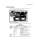
Page 58: ... Indicators Indicator Condition Meaning 1 Status Green Green Amber alternating Green flashing Amber Amber flashing Off Normal operation Power supply failed to restart after a prolonged fault Power supply will restart within 20 seconds Fault detected in this power supply Failed self test System in standby mode or interlock s disabled 2 AC Power Green Off AC power is connected to this power supply N...

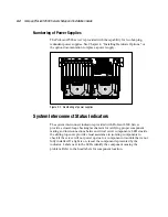
Page 59: ...The system interconnect indicators provided with ProLiant 8500 Server provide a closed loop checking mechanism for verifying proper component mating and interconnections between critical server components LEDs inside the sliding top cover provide visual assistance in isolating components to check if the server will not power up due to a component or module that is not fully installed If a light is...

Page 60: ... 6 Processor 4 t SCSI backplane 1 7 Processor 3 y SCSI backplane 2 8 Processor 2 u System Reset2 9 Processor 1 Note 1 AC power to the system has been cut to avert imminent component damage and data loss Reasons for this could include the failure of the terminator PPM the fan controller has stopped responding or the system has recorded a temperature violation Note 2 A power supply has stopped provi...

Page 61: ... switches Slide top access panel toward the front of the server Fans 1 and 2 Slide top access panel toward the front of the server Processor CPU sockets Remove Processor and Memory Module Processor and Memory Module Processor bus core ratio switches Remove Processor and Memory Module Cache Accelerator Remove Processor and Memory Module Memory DIMMs Open Processor and Memory Module to first stop Re...

Page 62: ...ace the hot plug fans and hot plug PCI boards as described in Chapter 4 Installing Hardware Options Removing the I O Module Use the procedure in the preceding section Accessing the I O Module to install or replace hot plug fans or hot plug PCI boards CAUTION Do not attempt to open any of the three modules while power is applied to the system They are not hot pluggable Immediate system shutdown and...

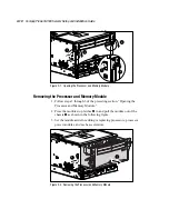
Page 63: ...p of the levers downward 2 as shown in the following figure 1 2 Figure 3 5 Removing the I O Module 3 Pull the I O Module out of the chassis until it reaches the module stop latch 4 Press the module stop latches in and pull the module out of the chassis as shown in the following figure 2 1 Figure 3 6 Removing the I O Module from the chassis ...

Page 64: ...ing Hardware Options for Hot Plug procedures 7 To reassemble the server slide the module in until the ejectors begin to rotate Then push ejectors shut until they snap into place Opening the Processor and Memory Module CAUTION Do not attempt to open any of the three modules while power is applied to the system They are not hot pluggable Immediate system shutdown and loss of data will occur To open ...

Page 65: ...e 1 Follow steps 1 through 3 of the preceding section Opening the Processor and Memory Module 2 Press the module stop latches 2 in and pull the module out of the chassis 1 as shown in the following figure 3 Set the module aside for adding or replacing processors processor power modules and cache accelerators 1 2 Figure 3 8 Removing the Processor and Memory Module ...

Page 66: ... network inventory and tracking purposes Compaq ProLiant 8500 servers are shipped with this feature disabled You can enable the feature using the System Configuration utility Removing the Media Module CAUTION Do not attempt to open any of the three modules while power is applied to the system They are not hot pluggable Immediate system shutdown and loss of data will occur To remove media module 1 ...

Page 67: ...or CD ROM drive as described in Chapter 4 Installing Hardware Options WARNING To reduce the risk of personal injury from hot surfaces allow the internal system components to cool before touching them NOTE The top panel labels provide instructions on installing processors DIMMs processor power modules and hard drives 6 To reassemble the server slide the module in until the ejectors begin to rotate ...

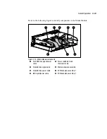
Page 68: ...e 1 2 3 4 5 6 7 8 Figure 3 10 Media Module components 1 CD ROM drive signal power cable 5 Power switch LED and thermistor cable 2 Diskette drive signal cable 6 Media backplane assembly 3 Diskette drive power cable 7 SCSI backplane assembly 1 4 IMD signal power cable 8 SCSI backplane assembly 2 ...

Page 69: ...risk of personal injury or damage to the equipment heed all warnings and cautions throughout the installation instructions WARNING To reduce the risk of personal injury or damage to the equipment the installation of options other than hot plug power supplies and hot plug hard drives should be performed only by individuals who are qualified in servicing computer equipment and trained to deal with p...

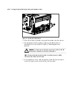
Page 70: ... or damage to the equipment Install the power supply before connecting the power cord to the power supply Unplug the power cord before removing the power supply from the server Disconnect power from the server by unplugging all power cords from either the electrical outlet or the server To replace a hot plug power supply with the system power ON 1 Remove the power cord from the power supply to be ...

Page 71: ...2 Removing a power supply 4 Remove the protective covers from the connector on the new power supply See the installation documentation that came with the power supply for more information Keep the protective covers for future handling 5 Lower the handle on the new hot plug power supply 6 Slide the hot plug power supply into the power supply cage pushing the spring loaded trap door open until the s...

Page 72: ...upply Leave an 8 inch service loop for the plug This will prevent the plug from becoming disengaged accidentally Figure 4 4 Securing the AC cord to the power supply 9 Verify the AC status LED is green If installation is performed with the system power on the power supply indicators should activate immediately 10 For a detailed description of the power supply indicators see Table 3 1 Power Supply I...

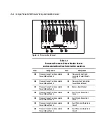
Page 73: ... the slowest processor Processors with different cache sizes may be mixed in groups of two For information on mixing cache sizes refer to the Compaq website www compaq com NOTE Be sure to keep processor terminator cards as processors are added The processor terminator cards can be used in the event a processor fails so that the server will run with the remaining processors Processor terminator car...

Page 74: ...Module Socket 2 Processor Socket 2 and associated Power Module Socket 9 Processor Bus Termination Power Module Socket 3 Processor Socket 3 and associated Power Module Socket Memory Board Socket 4 Processor Socket 4 and associated Power Module Socket q Bus 1 Cache Accelerator Socket 5 Processor Socket 5 and associated Power Module Socket w Bus 2 Cache Accelerator Socket 6 Processor Socket 6 and ass...

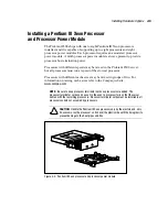
Page 75: ...n label located on the left side of the Processor and Memory Module For an overview of processor installation see the procedure below 1 If the server is on place it in Standby See Chapter 2 Server Installation 2 Remove the Processor and Memory module See Chapter 3 Server Operation WARNING To reduce the risk of personal injury from hot surfaces allow the internal system components to cool before to...

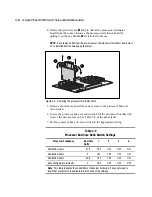
Page 76: ...oard for easier access to the processor bus core ratio switch 6 Locate the processor bus core ratio switch for the processor bus that will receive the new processor See Table 4 2 or the panel label 7 Set the processor bus core ratio switch to the appropriate setting Table 4 2 Processor Bus Core Ratio Switch Settings Processor Frequency Bus Core Ratio 1 2 3 4 450 MHz models 4 1 2 OFF ON OFF ON 500 ...

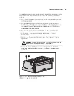
Page 77: ...socket Install 1 and secure the processor power module by rotating the ejector levers inward 2 You should hear the ejectors click into a locked position CAUTION The processor power module must be installed before the accompanying Pentium III Xeon processor Attempting to install the processor power module after the Pentium III Xeon processor has been installed could damage the electronic components...

Page 78: ...ection Installing the Cache Accelerator 10 Replace the Processor and Memory module into the chassis 11 Turn on the server See Chapter 2 Server Installation If the system does not power up open the top access and verify that the system interlock LEDs are normal See Table 3 2 System Interlock Status Indicators in Chapter 3 Server Operation 12 Verify that the processor was installed correctly Check t...

Page 79: ...r Cache Accelerator 2 1 10 8 7 6 5 4 3 2 9 13 14 11 12 Figure 4 11 Processor board layout Processors should be added to fill bus 1 before adding processors to bus 2 If processors occupy slots of both processor buses then the Cache Accelerators for both buses must be installed for proper operation To install the cache accelerator in the Processor and Memory module refer to one of the following inst...

Page 80: ...em components to cool before touching them 3 Loosen the thumbscrew of the middle air baffle and lift the baffle upward to allow access to the Cache Accelerator slots 1 2 3 Figure 4 12 Removing middle air baffle 4 Locate the Cache Accelerator slot is shown in the following figure NOTE The Cache Accelerator modules are keyed to ensure correct alignment ...

Page 81: ...d reconnect the power cord s 9 Turn on the server See Chapter 2 Server Installation SDRAM Memory You can expand computer memory by installing industry standard Dual Inline Memory Modules DIMMs into the memory expansion boards The following requirements must be met when installing additional memory Supports 100 MHz Registered SDRAM 128 MB 256 MB and 512 MB Will also support 1 GB DIMMs when they are...

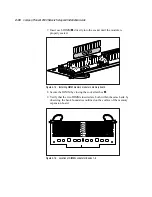
Page 82: ...er included in the shipping box and on the label located on the inside of the Processor and Memory module For an overview of memory installation see the following procedure Adding or Replacing Memory The memory board connects to the processor board which is located inside the Processor and Memory module To remove a memory board 1 If the server is on place it in Standby See Chapter 2 Server Install...

Page 83: ...the System Interconnect Status Indicators section in Chapter 3 Server Operation CAUTION The ejectors prevent the memory expansion board from lying completely flat Inserting a DIMM without counter pressure applied behind the socket to the back of the expansion board can cause the memory expansion board to flex and could result in damage Always support the memory expansion board or apply counter pre...

Page 84: ...eated 1 3 2 Figure 4 15 Installing DIMM memory module in memory board 8 Secure the DIMM by closing the socket latches 3 9 Verify that the two DIMMs inserted are both within the same bank by observing the bank boundaries outlined on the surface of the memory expansion board 1 2 3 4 5 6 7 8 Figure 4 16 Location of DIMM sockets for Banks 1 8 ...

Page 85: ...ry was installed correctly by reviewing the POST messages on the system console or memory information under the System Information Menu of the IMD See Chapter 6 Integrated Management Log Mass Storage The following sections provide overviews for installing hard disk drives CD ROM drives and external storage devices The ProLiant 8500 supports up to four 1 inch Ultra2 Single Connector Assembly SCA ho...

Page 86: ... 3 4 5 6 7 Figure 4 17 Four 1 inch hot plug hard drives installed in media module 1 Hot plug hard drive SCSI ID 0 5 Integrated Management Display if installed 2 Hot plug hard drive SCSI ID 1 6 Integrated Diskette drive 3 Hot plug hard drive SCSI ID 3 7 Integrated CD ROM drive 4 Hot plug hard drive SCSI ID 2 CAUTION If a hard drive is removed a blanking panel must be added for static immunity and a...

Page 87: ... in the lowest numbered bay If several drives are installed the system boot drive should be installed in the lowest numbered bay In order to maintain proper system cooling blanking panel should be installed in unused drive bays The server has one embedded Integrated Smart Array Controller Ultra2 support The integrated controller is hardwired through an array enabler board to the four SCSI hard dri...

Page 88: ...lure to do so could result in loss of data or damage to equipment To install a hot plug SCSI hard drive 1 Remove the blanking panel in an unused drive bay by pushing the side of the retaining clip inward then pulling the blanking panel outward 2 1 Figure 4 18 Removing a hard drive blanking panel 2 Push the release button on the left of the new drive and rotate the hot plug drive ejector lever outw...

Page 89: ...he ejector lever inward 2 as shown below 1 2 Figure 4 19 Installing a SCSI hard drive CAUTION Before removing any hot plug hard drive read the important guidelines in the following two sections 5 To remove a hot plug SCSI hard drive push the release button on the left of the drive and rotate the hot plug drive ejector lever outward to unlock Pull the drive out of the drive bay ...

Page 90: ... Power Online and 3 Fault These indicators are shown in the following figure The following table explains how to interpret the indicators 1 2 3 Figure 4 20 Hot Plug SCSI hard drive indicators Table 4 3 Interpreting Hot Plug SCSI Hard Drive Indicators 1 2 3 Indicator Meaning Off Off Off OK to remove drive if not part of a fault tolerant configuration Off Off On OK to remove failed drive X On X Driv...

Page 91: ...be flashing green whenever it is being rebuilt A replaced drive is restored from data stored on the other drives Never turn a ProLiant Storage System off while the server controlling it is powered on Doing so will cause the server s Smart Controller to mark the drives as failed This could result in permanent data loss If an online spare drive is installed wait for it to complete rebuilding before ...

Page 92: ...or information on adding or removing PCI Hot Plug Expansion Boards see the Adding Expansion Boards section later in this chapter To install an external storage device refer to the installation documentation that came with the external storage device The following illustration provides only an overview of this installation 1 If the server is on place it in Standby mode and disconnect the power cord...

Page 93: ...under some operating systems Hot upgrade of adapters This feature allows you to replace an adapter with a different adapter without powering down the server PCI Hot Plug is backward compatible though system components fit into one of two categories hot plug aware or non hot plug aware The following are required in the server for complete PCI Hot Plug capability PCI Hot Plug system hardware availab...

Page 94: ...the top access panel as described in Chapter 3 Server Operation WARNING To reduce the risk of personal injury from hot surfaces allow the internal system components to cool before touching them 1 2 3 4 5 6 7 8 9 10 11 Figure 4 22 Top view of I O slots The I O expansion slots are distributed among three I O buses For more information about these buses refer to the section titled Bus Distribution la...

Page 95: ... shown in the following figure for one slot provide a visual reference of the status of each slot The LEDs are viewed from the rear of the server or by opening the top access panel 1 2 Figure 4 23 PCI Hot Plug LED indicators from rear of server 1 3 2 Figure 4 24 PCI Hot Plug LED indicators in the I O Module ...

Page 96: ...es attention There may be a problem with the slot the PCI board or the driver Check the green LED before opening the slot Flashing No Power to slot is being turned OFF or ON This process may take several minutes DO NOT open the slot release lever until the green LED is completely off X Off Yes You can replace or remove board in this slot only PCI Hot Plug Operating System Support Software support ...

Page 97: ...to power up the slot Software Components The software components include the Compaq PCI Hot Plug Utility the Compaq Remote Monitor service CPQRCMC the Compaq Systems Management driver SYSMGMT SYS and hot plug aware drivers The Compaq PCI Hot Plug Utility allows you to monitor and control PCI Hot Plug slots You can accomplish the following tasks View the current power and fault status of all PCI Ho...

Page 98: ...ware configuration Confirm the auto detect by looking at the hardware The presence of multiple network adapters may complicate the network setup phase PCI Hot Plug technology for Windows NT 4 0 relies on the presence of the Windows NT Remote Procedure Calls RPC service For more information see the Windows NT documentation PCI Hot Plug technology for Windows NT 4 0 requires installation of the Comp...

Page 99: ...th PCI Hot Plug and will continue to work in non hot plug environments Software Components Novell uses a central component the Novell Event Bus to facilitate communications between different software modules The Event Bus is implemented as a NetWare Loadable Module NLM allowing you to implement PCI Hot Plug on existing versions of NetWare Listed below are the components of the PCI Hot Plug archite...

Page 100: ...in Manager is incorporated into SCO s existing system managed framework called SCO Admin The Hot Plug Controller interface tracks system component information as well as manages the actions required for hot plug functions The Hot Plug Controller Interface processes Hot Plug Services Library HPSL requests by interfacing with the Netscape AutoConfig Subsystem Using the existing Compaq Support Softwa...

Page 101: ... Plug Technology with SCO SoftwareArchitecture found on the Compaq website at www compaq com For further information on the PCI Hot Plug Button and PCI Hot Plug software see the PCI Hot Plug Important Facts in the online PCI Hot Plug Administration Guide on the Systems Reference Library CD Supported I O Expansion Boards The I O board of the ProLiant 8500 has eleven PCI Hot Plug expansion slots The...

Page 102: ...numbers Table 4 5 Bus Distribution of PCI Hot Plug Slots Bus Number Associated PCI Bus PCI Hot Plug Slot No 1 PCI Bus 1 64 Bit 33 MHz Slots 7 through 9 2 PCI Bus 2 64 Bit 33 MHz Slots 1 through 6 3 PCI Bus 3 64 Bit 66 MHz Slots and q Adding Expansion Boards Non Hot Plug Expansion Boards You can use non hot plug expansion boards in the ProLiant 8500 server but you must install them according to the...

Page 103: ...lots are powered up at boot and opening the slot release lever will cause the slot to be powered off If you add a board in this manner you will not be able to power up the slot Use the following procedure to add a PCI expansion board into PCI Hot Plug slots 1 through 11 See Figure 4 23 Figure 4 24 and Table 4 3 for definitions of the PCI Hot Plug LEDs 1 Open the top access door 2 If the slot PCI H...

Page 104: ... of the expansion slot 4 Remove the expansion slot cover 3 1 3 4 2 Figure 4 26 Preparing the hot plug expansion slot for installation 5 Open the air baffle 4 6 Insert the PCI expansion board into the appropriate expansion slot pushing firmly until securely seated 3 1 2 Figure 4 27 Inserting the PCI expansion board 7 Connect the expansion board I O cable as appropriate ...

Page 105: ...keepers is especially important when expansion boards are added or the server is moved 10 Activate power to the slot through the PCI Hot Plug software application or by pressing the PCI Hot Plug Button above with the corresponding I O expansion slot 1 3 2 Figure 4 28 Activating the PCI Hot Plug Button 11 Review the amber LED and green LED indicators for slot status The green LED will flash during ...

Page 106: ...stem power down and subsequent data loss could occur 3 When the slot s green LED is off disconnect cables to the PCI board 4 Open the slot release lever and the L shaped slot keeper 5 Remove or replace the board 6 If only removing the board install an expansion slot cover 7 If replacing the board connect the cables to the PCI board 8 Close the slot release lever Ensure that the lever latches into ...

Page 107: ... fan and fan is functional Amber light 2 fan has failed 2 1 Figure 4 29 Hot plug fan LED indicators NOTE The hot plug fan LEDs are not part of the fan housing The figure above shows the LEDs as if the fan were installed in the server CAUTION Never remove both hot plug fans while the server is powered up Overheating and damage to hardware could result If the appropriate Compaq software drivers are ...

Page 108: ... 2 1 2 Figure 4 30 Removing hot plug I O Fan 2 3 Lower the new hot plug fan into the I O Module until it rests on the I O board connector holding the locking latches Push the fan into the connector and release the locking latches to engage the fan 1 2 Figure 4 31 Installing a new hot plug fan 1 4 Verify that the fan is producing airflow and that the LED is green 5 Close the top access door ...

Page 109: ... 16 MB total memory 12 MB Read Ahead Cache Support for up to four internal Ultra2 SCSI Hot Plug drives in RAID 0 1 0 1 and 5 External connector supports external tape drives for backup of the internal drives Migration from any RAID level to any RAID level Migration from any stripe size to any stripe size PreFailure notification and PreFailure Warranty through Compaq Insight Manager On line spares ...

Page 110: ...the Integrated Array Bypass Kit and an optional controller such as the Compaq 3200 Array Controller See the following section Installing the Integrated Array Bypass for installation instructions For external RAID support use an array controller such as the Compaq 3200 Array Controller The Option ROM based Array Configuration Utility is used to help you configure the hardware in the way that best s...

Page 111: ... Array Enabler Board in the I O Module The Integrated Array Bypass kit allows you to replace the Array Enabler Board with a connector and cable that you can connect to an optional controller board such as the Compaq 3200 Array Controller CAUTION It is recommended that any time you move drive arrays or change your configuration you should back up the data WARNING To reduce the risk of personal inju...

Page 112: ...lation Guide 5 Remove the Array Enabler Board as shown in the following figure 1 2 Figure 5 2 Removing the Array Enabler Board 6 Install the Integrated Array assembly as shown in the following figure Figure 5 3 Installing the Integrated Array assembly ...

Page 113: ...optional array controller board as shown in the following figure 1 2 Figure 5 5 Connecting the Integrated Array Bypass assembly cable NOTE The actual appearance and routing of the cable in the preceding figure depends on which slot the optional array controller board occupies 9 Close the top access panel and power up the server 10 Configure the new controller with the ACU as described later in thi...

Page 114: ... to bypass the Option ROM Based Configuration Utility You can configure the internal drives later using the Array Configuration Utility while running SmartStart At the initial screen press F10 to run the utility If there are no logical drives detected you will be prompted to indicate the operating system to be used You are then prompted to choose the logical drive configuration The utility will us...

Page 115: ...configurations Provides express or custom initial configuration Supports adding additional capacity Supports RAID 0 1 0 1 and 5 fault tolerant configurations Supports Raid level and stripe size migration Helps optimize your array configuration with configuration Wizards Sets drive rebuild priorities Allows on line spare hot spare configuration Allows separate fault tolerance configuration on a log...

Page 116: ...nd its drive arrays If the arrays are unconfigured or if the configuration is less than optimal the configuration wizard takes over to guide you through the configuration process On line Help Press the F1 key or the click the Help button to activate context sensitive help for each screen A status bar at the bottom of the screen also provides immediate help messages describing the current selection...

Page 117: ...PORTANT Logical drive extension is not supported by all operating systems Only extend logical drives that are used with an operating system that supports extension Extending Logical Drives Operating Systems The following operating systems support logical drive extension Microsoft Windows NT 4 0 NetWare 5 0 OS 2 WarpConnect OS 2 WarpServer OS 2 WarpServer Advanced OS 2 WarpServer SMP OS 2 Warp 4 0 ...

Page 118: ...sage that describes the problem Error and warning messages include instructions to correct configurations If a warning message indicates Internal Error Has Occurred and cites an error code number the problem requires assistance from Compaq technical support See About This Guide at the beginning of this book for technical support phone numbers Alternate Sources of the Array Configuration Utility Ac...

Page 119: ...NSSD diskettes have an ARRAY RDM readme file to access instructions on loading and using CPQONLIN NLM SmartStart and Support Software CD You can run the Array Configuration Utility directly from the SmartStart and Support Software CD 1 Insert the SmartStart and Support Software CD in the CD drive and power up the server A menu is displayed 2 Select the Array Configuration Utility 3 After completin...

Page 120: ...onfigured the SmartStart program automatically creates a system partition and installs the Compaq System Configuration Utility and other Compaq utilities in that partition NOTE Until you run the System Configuration program an information message indicating that you are running with a default configuration will occur each time you boot the system See Powering Up Your Server in Chapter 2 for more d...

Page 121: ... 1 Installing a CD in the CD ROM drive When the CD ROM busy indicator is lit the SmartStart installation sequence begins To configure the system and load the operating system refer to the SmartStart documentation provided in the Server Setup and Management pack shipped with your server To manage the system refer to the Compaq Management CD provided in the Server Setup and Management pack shipped w...

Page 122: ...amp with one minute granularity Events listed in the Integrated Management Log are categorized as one of four event severity levels Status Informational indicates that the message is informational only Repaired indicates that corrective action has been taken Caution indicates a non fatal error condition Critical indicates a component failure The Integrated Management Log requires Compaq Operating ...

Page 123: ... The following sections provide information on navigating and using the menus Configuring the Integrated Management Display The Compaq Integrated Management Display can be configured to display a variety of menus that you can customize to meet your specific needs This section provides information on how to configure and customize the Integrated Management Display Setup with the System Configuratio...

Page 124: ...it Details and press Enter 6 Scroll down until you find the section entitled Embedded Compaq IMD Module 7 Highlight the field that you want to modify You must press Enter to edit the highlighted item then type the text for that field After entering the text press Enter to accept the modifications Each field is discussed in detail later in this section See Customizing Management Display Fields 8 Re...

Page 125: ...upgrade your System Configuration Utility at this time Customizing Management Display Fields You can customize many of the fields shown on the Integrated Management Display The following sections define each of the menu choices and include examples of some fields Idle Screen Text After the display has been idle for five minutes the Integrated Management Display shows the following default screen t...

Page 126: ...your server You can enter up to 4 lines of 14 characters each Server Information Server Name Enter up to 2 lines of no more than 14 characters each An example might be to name the server by department for example CUST SERVICE WESTERN REGION Asset Tag Enter the server asset tag Enter up to 2 lines of 16 characters each Primary Operating System Enter the primary operating system of the server for ex...

Page 127: ...aracters each Other This is a user defined field You can enter any additional administrator information An example might be listing an additional administrator that serves as a backup to the primary administrator Enter up to 2 lines of no more than 14 characters each Service Information Name This field contains the name of the service provider Enter up to 2 lines of no more than 14 characters each...

Page 128: ...user defined fields customized during configuration the Integrated Management Display automatically provides the following standard fields System Information Events Selecting this menu choice enables you to scroll through a list of all error events starting with the most recent event ROM Date This is the month date year of the current server ROM Bootblock Date This is the month date year of the cu...

Page 129: ...g the display and rebooting the server a series of server POST Power On Self Test operations appears The first screen you will see after rebooting the server shows the model number and IMD firmware revision of your display then the POST screen appears During POST the display indicates that the server test is in progress by a spinning bar beside the menu item When the test is finished the Integrate...

Page 130: ...Meaning Right Arrow Selector arrow shows current menu item Press Enter on the IMD to select the menu item to the right of this arrow Up Arrow If present in upper right corner indicates previous information exists Press the Up Arrow on the IMD to view the information Press and hold the button to scroll Down Arrow If present in lower right corner indicates more information exists Press the Down Arro...

Page 131: ...e Down and Up arrow keys and allow you to move through the menu screens and choose menu items The right button acts as an Enter key and allows you to travel down through the menus The left button acts as an Escape key and allows you to travel back up the menu COMPAQ PROLIANT XXXX LCD 011 EPS 1 2 3 4 ESC Figure 7 2 Integrated Management Display buttons ...

Page 132: ...information menu before the IMD will allow you to move on to other menu choices The display will not allow you to escape out of the Unviewed Events section until you have examined all of the information stored there After you have reviewed the events you are able to proceed with normal display operation Menu Structure The following outline shows the structure of each menu and submenu in the order ...

Page 133: ...lation Guide Operating System Other Administrator Name Phone Pager Other Service Name Phone Pager Other Custom Menu Item if entered Custom Menu Screen if entered System Information ROM Date Bootblock Date Memory Processors Contrast Contrast Other Info ...

Page 134: ...ou can lower the severity of the event Viewing the Event List 1 From Compaq Insight Manager select the appropriate server then select View Device Data 2 The selected server is displayed with buttons around its perimeter 3 Select the Recovery button 4 Select Integrated Management Log NOTE You can only view the list from the Recovery Integrated Management Log screen To print the list follow the inst...

Page 135: ... information on installing and running the Survey Utility After you have run the Survey Utility you can view the Integrated Management Log by loading the output of the utility typically called survey txt into a text viewer such as Microsoft Notepad The event list follows the system slot information Once you have opened the text file you can print it using the print feature of the viewer For more i...

Page 136: ...no main power applied to the system power supplies If the System LED is amber check the System Interconnect Status Indicators explained later in this chapter If the System LED blinks once every 10 20 seconds the system is trying to start but may have a short Refer to the System Short section in the Compaq Servers Troubleshooting Guide 2 Check the power supplies The following settings indicate that...

Page 137: ...or the IMD memory test message The monitor shows the memory count and the memory initialization 4 Observe the memory count displayed 5 Check for the IMD BIOS message The monitor shows the number of processors their speed and their cache size 6 Check for IMD messages about a Drive Array b Floppy Drive c Option ROM d SCSI device Make sure each green LED on the PCI Hot Plug Interface Board is on both...

Page 138: ...nts are not installed or are installed incorrectly The system interconnect status indicators provided with ProLiant 8500 Server provide a closed loop checking mechanism for verifying proper component mating between critical server components These indicators are located in the I O Module in front of the system fans They are operated using standby power provided by the power supplies If a light is ...

Page 139: ...cessor 5 r Media Module 6 Processor 4 t SCSI backplane 1 7 Processor 3 y SCSI backplane 2 8 Processor 2 u System Reset2 9 Processor 1 Note 1 AC power to the system has been cut to avert imminent component damage and data loss Reasons for this could include the failure of the terminator PPM the fan controller has stopped responding or the system has recorded a temperature violation Note 2 A power s...

Page 140: ...ine During the Power On Self Test POST press F10 to start the Compaq System Diagnostics 4 At the Main Menu select Diagnostics and Utilities 5 At the Diagnostics and Utilities menu select Test Computer 6 Select a test Quick Check runs a select set of tests The time required for the test depends on the server configuration it could require up to two hours This test does require less time than the Au...

Page 141: ...s product always refer to this Series Number This series number should not be confused with the marketing name or model number for your Compaq ProLiant 8500 server Federal Communications Commission Notice Part 15 of the Federal Communications Commission FCC Rules and Regulations has established Radio Frequency RF emission limits to provide an interference free radio frequency spectrum Many electro...

Page 142: ...a commercial environment This equipment generates uses and can radiate radio frequency energy and if not installed and used in accordance with the instructions may cause harmful interference to radio communications Operation of this equipment in a residential area is likely to cause harmful interference in which case the user will be required to correct the interference at personal expense Declara...

Page 143: ... EMI connector hoods in order to maintain compliance with FCC Rules and Regulations Canadian Notice Avis Canadien Class A Equipment This Class A digital apparatus meets all requirements of the Canadian Interference Causing Equipment Regulations Cet appareil numérique de la classe A respecte toutes les exigences du Règlement sur le matériel brouilleur du Canada Mouse Compliance Statement This devic...

Page 144: ...Directive 73 23 EEC issued by the Commission of the European Community Compliance with these directives implies conformity to the following European Norms in brackets are the equivalent international standards EN55022 CISPR 22 Electromagnetic Interference EN50082 1 IEC801 2 IEC801 3 IEC801 4 Electromagnetic Immunity EN60950 IEC950 Product Safety Japanese Notice Taiwanese Notice ...

Page 145: ... try to open the laser device enclosure There are no user serviceable components inside Do not operate controls make adjustments or perform procedures to the laser device other than those specified herein Allow only Compaq Authorized Service technicians to repair the laser device Compliance with CDRH Regulations The Center for Devices and Radiological Health CDRH of the U S Food and Drug Administr...

Page 146: ...This label indicates that the product is classified as a CLASS 1 LASER PRODUCT This label appears on a laser device installed in your product Laser Information Laser Type Semiconductor GaAIAs Wave Length 780 nm 35 nm Divergence Angle 53 5 degrees 0 5 degrees Output Power Less than 0 2 mW or 10 869 W m 2 sr 1 Polarization Circular 0 25 Numerical Aperture 0 45 inches 0 04 inches ...

Page 147: ...er WARNING Your computer contains an internal Lithium Manganese Dioxide or a Lithium Vanadium Pentoxide or an alkaline battery pack There is risk of fire and burns if the battery pack is not handled properly To reduce the risk of personal injury Do not attempt to recharge the battery Do not expose to temperatures higher than 60 C Do not disassemble crush puncture short external contacts or dispose...

Page 148: ...damage may reduce the life expectancy of the device To prevent electrostatic damage observe the following precautions Avoid hand contact by transporting and storing products in static safe containers Keep electrostatic sensitive parts in their containers until they arrive at static free workstations Place parts on a grounded surface before removing them from their containers Avoid touching pins le...

Page 149: ...the ground cords To provide proper ground wear the strap snug against the skin Use heel straps toe straps or boot straps at standing workstations Wear the straps on both feet when standing on conductive floors or dissipating floor mats Use conductive field service tools Use a portable field service kit with a folding static dissipating work mat If you do not have any of the suggested equipment for...

Page 150: ...equirements The requirements listed below are applicable to all countries The length of the power cord must be at least 6 0 feet 1 8 m and a maximum of 12 feet 3 7 m The power cord set must be approved by an acceptable accredited agency responsible for evaluation in the country where the power cord will be used The power cord set must have a minimum current capacity and nominal voltage rating of 1...

Page 151: ...agency in your country Table C 1 Power Cord Set Requirements By Country Country Accredited Agency Applicable Note Numbers Argentina IRAM 1 Australia EANSW 1 Austria OVE 1 Belgium CEBC 1 Canada CSA 2 Chile N A 4 China CCEE 5 Denmark DEMKO 1 Finland SETI 1 France UTE 1 Germany VDE 1 India IS 7 Italy IMQ 1 Japan JIS 3 Korea KIATECH 6 Norway NEMKO 1 continued ...

Page 152: ...gistration number in accordance with the Japanese Dentori Law Flexible cord must be Type VCT or VCTF 3 conductor 1 0 mm2 conductor size Wall plug must be a two pole grounding type with a Japanese Industrial Standard C8303 7A 125V configuration 4 Flexible cord must be Type SJT No 16 AWG 3 conductor Wall plug must be the 3 pin Italian style plug conforming to th4e CEI 23 16 VII standard 5 Flexible c...

Page 153: ...to 120 V 200 to 240 V Rated Input Frequency 50 to 60 Hz 50 to 60 Hz Rated Input Current 8 A 10 A Power Supply Output Power per power supply Low Range High Range Rated Steady State Power 500 W 1150 W Maximum Peak Power 549 W 1150 W Temperature Range Operating 50 to 95 F 10 to 35 C 1 Shipping 22 to 122 F 30 to 60 C Relative Humidity noncondensing Operating 10 to 90 10 to 90 Nonoperating 5 to 90 5 to...

Page 154: ...1 11 attaching cable management bracket 2 23 slide rail assembly 2 16 2 19 slide rails 2 13 2 14 authorized service provider 1 9 Auto Line Sensing 1 7 Automatic Server Recovery See ASR 2 B battery recycling or disposal A 7 battery replacement warnings A 7 blanking panels 4 19 boot block 1 8 default configuration 6 1 straps using B 2 System Configuration Utility 6 1 buses PCI local bus 1 6 PCI iden...

Page 155: ...anagement 1 7 switches accessing 3 6 System Configuration Utility 1 10 system load 1 7 tools 1 10 utility 6 1 utility installing 1 11 utility Option ROM based 5 6 wizard 5 8 wizard physical drive not in use 5 8 connectors external SCSI 2 26 keyboard 2 26 mouse 2 26 parallel port 2 26 rear panel 2 26 serial 2 26 VHDCI 1 6 video port 2 26 controllers 10 100 TX UTP 1 6 Fast SCSI 2 4 30 NetFlex 3 4 30...

Page 156: ...orrecting Memory See ECC error events IMD 7 11 errors 105 1 8 server integrity 1 8 ESD See electrostatic discharge Ethernet 100TX Ethernet 1 6 10BaseT Ethernet 1 6 European Union Notice A 4 event description 1 13 Insight Manager 7 2 expansion boards non hot plug 4 25 expansion slots See I O expansion slots external SCSI connector 2 26 F F2 key 4 23 fans accessing 3 6 LEDs 4 39 replacing 4 39 statu...

Page 157: ... 2 4 39 features 1 4 hot replacement 4 29 Novell NetWare 4 31 operating system support 4 28 overview 1 4 overview 4 25 power supplies 4 2 requirements 4 25 Hot Plug SCO UNIX 4 32 slots 34 bit 1 4 slots 64 bit 1 4 technology brief 4 30 4 31 utility 1 4 4 29 Windows NT 4 29 hot surfaces xi 4 7 4 14 http www compaq com xiii I I O expansion boards 1 10 installing 4 35 overview 4 25 removing 4 40 I O e...

Page 158: ... viewing 7 2 IML events 7 2 overview 1 12 7 1 server management 1 10 1 12 viewing 7 2 indicators Interconnect Status 3 4 power supplies 4 4 System Interconnect Status 8 3 Insight Manager IMD 7 13 information 1 12 installation 2 2 printing event list 7 13 server management 1 10 1 11 viewing event list 7 13 INSPECT utility 1 11 installation materials 2 7 installing cable management arm 2 24 cable ma...

Page 159: ... 29 System Interconnect Status 8 3 load balancing 1 7 locating cache accelerator sockets 4 11 I O expansion slots 4 26 memory socket 4 6 processor slots 4 6 Log Integrated Management Log See IML logical drive extension defined 5 9 M maintenance routine 1 14 management CD 2 2 server 1 12 server 1 10 web based 1 12 Management CD 6 2 mass storage installation 4 17 media drive bays accessing 3 6 featu...

Page 160: ...on boards 4 25 nonvolatile memory 1 11 Novell Configuration Manager NCM 4 31 Configuration Manager Console NCMCON 4 31 Novell Event Bus NEB 4 31 Open Data Link Interface 4 31 Software Support Diskette 4 31 NT See Windows NT NT SSD 4 30 NWPA 4 31 O ODI See Open Data Link Interface OEM Specific System Bus Driver SBD 4 31 OFF 2 29 ON 2 29 online help 5 8 online migration changing RAID level 5 10 chan...

Page 161: ...tes 8 5 supplies options 2 7 supplies supported 1 7 supply indicators green 3 3 power supply indicators green amber alternating 3 3 supply indicators normal operation 3 3 supply indicators 3 3 power cord set agency approval C 1 applicance coupler specifications C 1 cable length C 1 cable specifications C 3 country specific requirements C 2 current capacity C 1 obtaining additional information C 1 ...

Page 162: ...es 4 23 I O expansion boards 4 40 Media module 3 11 power 3 2 Processor and Memory module 3 10 requirements airflow 2 6 Hot Plug 4 25 memory 4 13 power 2 2 space 2 3 temperature 2 2 tools 2 7 retention clip 2 27 RJ 45 connectors 1 6 ROM corrupted 1 8 faulty 1 8 flashing 1 9 recovering 1 8 remote flash redundant 1 8 system 2 28 ROMPaq 1 8 1 11 1 14 RPC See Windows NT Remote Procedure Calls RPC S SB...

Page 163: ...ntainers storing products in B 1 transporting products in B 1 Support Software for Microsoft Windows NT 4 0 See NT SSD Support Software for Unix See SSD Survey Utility 7 2 7 14 switch and jumper settings 1 10 switches configuration 3 6 On Standby 2 29 Power On Standby 3 2 processor board 2 2 processor bus core ratio 3 6 4 8 system configuration switch 2 2 verifying 2 2 symbols in text x symbols on...

Page 164: ...ility xii technical support xiii temperature maximum recommended ambient TMRA 2 4 operating maximums 2 5 rack requirements 2 4 terminator cards 4 5 TMRA 2 4 See temperature maximum recommended ambient tools conductive field service type B 2 required for installation 2 7 top access panel general 3 6 opening 3 7 troubleshooting hard drive LEDs 8 2 IMD 8 2 PCI Hot Plug LEDs 8 2 power supplies 8 1 sta...

Page 165: ...pment damage xii grounding plug xii hazardous energy levels xi hot surfaces 3 9 3 11 3 12 4 26 warnings improper repairs xi personal injury ix xi power cord grounding plug 3 2 power cords 3 2 power supplies 2 27 voiding warranty xi warranty 1 9 web based management 1 12 website PCI Hot Plug information 4 33 registration 1 14 server and option information 1 9 Windows NT support information 4 30 Wid...

Reviews: