background image

5-2


Network Communications

Writer: Erica T Blakeney   Project: Compaq Professional Workstation 5100 Reference Guide   Comments: 299348-003

File Name: F-CH05.DOC   Last Saved On: 3/12/98 11:44 AM

COMPAQ CONFIDENTIAL - NEED TO KNOW REQUIRED

Identifying the Ethernet Connectors

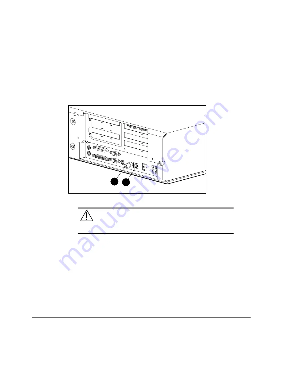
The following Ethernet connectors  are located on the rear panel of the
workstation:

■ 

RJ-45 (8-pin) connector 

■ 

BNC (thin-coax cable) connector 

2

1

Figure 5-1.    Identifying the Ethernet connectors

WARNING:

     To reduce the risk of electrical shock, fire, or

damage to the equipment, do not plug telecommunications/
telephone connectors into the network interface controller (NIC)
receptacles.

Summary of Contents for Compaq PW5100

Page 1: ...e the following components workstation cover expansion board bracket 3 Locate the SW1 switch on the system board on 1 2 3 4 5 6 A C A C A C A C A C A C A C A C A C A C A C A C A C A C A C A C A C A C...

Page 2: ...r On Password and the Setup Password Be sure to reestablish both passwords 7 Turn off the workstation once more Disconnect the power cord from the grounded AC outlet and from the power connector on th...

Page 3: ...Professional Workstation 5100 Reference Guide Third Edition April 1998 Part Number 299348 003 Compaq Computer Corporation...

Page 4: ...or reproduced in any form without prior written consent from Compaq Computer Corporation 1998 Compaq Computer Corporation All rights reserved Printed in the U S A The software described in this guide...

Page 5: ...xiii Getting Help xiv Compaq Website xiv Telephone Numbers xiv Chapter 1 Product Features Standard Features 1 2 Processors 1 2 Memory 1 2 Expansion Slots 1 2 Drive Controller 1 3 Network Controller 1...

Page 6: ...ies Menu 2 1 Computer Setup 2 2 Computer Checkup TEST 2 4 View System Information INSPECT 2 6 Create a Diagnostics Diskette 2 6 Manage a Diagnostics Partition 2 7 Exit from This Utility 2 7 ROM BIOS 2...

Page 7: ...Software CD and Compaq Website 4 10 Asset Management 4 11 Compaq Diagnostics for Windows NT 4 11 Compaq Insight Manager and Insight Management Agents 4 13 Chapter 5 Network Communications Identifying...

Page 8: ...13 Important Guidelines for Expansion Board Cage Replacement 7 14 Removing the System Board Tray 7 15 Identifying System Board Components 7 16 Chapter 8 Memory Upgrades Installing Additional Memory 8...

Page 9: ...1 3 Upgrading Memory 11 3 Installing an Additional Controller 11 3 Resolutions and Color Support 11 4 MVP Workstation Graphics Controller 11 7 Connecting the Four Port Splitter Cable 11 7 Installing t...

Page 10: ...18 CD ROM Drive Problems 13 19 Appendix A Regulatory Compliance Notices Federal Communications Commission Notice A 1 Class A Equipment A 1 Class B Equipment A 2 Modifications A 2 Cables A 2 Declarati...

Page 11: ...3 12 98 11 10 AM Appendix B Electrostatic Discharge Grounding Methods B 1 Appendix C Power Cord Set Requirements General Requirements C 1 Appendix D POST Error Messages Error Messages D 1 Appendix E...

Page 12: ...conventions to distinguish elements of text Keys Keys appear in boldface A plus sign between two keys indicates that they should be pressed simultaneously USER INPUT User input appears in a different...

Page 13: ...rmation or specific instructions NOTE Presents commentary sidelights or interesting points of information Product Safety Information Symbols on Equipment These icons may be located on equipment in are...

Page 14: ...rface to cool before touching Power Supplies or Systems marked with these symbols indicate the equipment is supplied by multiple sources of power WARNING To reduce the risk of injury from electrical s...

Page 15: ...s You can access the Compaq website by logging on to the Internet at http www compaq com Telephone Numbers For the name of your nearest Compaq Authorized Reseller In the United States call 1 800 345 1...

Page 16: ...41 796 5151 Australia 61 2 9911 1999 Fax 61 2 9911 1800 Austria 431 87816 0 Fax 431 878 16 80 CompaqCare Center 0222 8716 16 Belgium 322 716 9511 Fax 322 725 2213 CompaqCare Center 02 716 9696 Brazil...

Page 17: ...0 615 599 Fax 358 0 6155 9898 CompaqCare Center 358 9800 206 720 QuickLine 358 0 6155 9870 France 331 4133 4100 Fax 331 4133 4400 CompaqCare Center 331 4133 4455 QuickLine 331 6986 7396 FaxPaq Minitel...

Page 18: ...ine 02 89 200 222 Japan 3 5402 5700 Fax 3 5402 5964 Korea 82 2 3470 0766 Fax 82 2 523 3576 Malaysia 603 7541122 Fax 603 7548600 Mexico 525 229 7900 Fax 525 229 7959 Middle East 971 4 818 100 Fax 971 4...

Page 19: ...ional Headquarters 65 336 3333 Fax 65 750 4627 Compaq Computer Asia Pacific Local Subsidiary including regional sales for South Asia Indochina Brunei Indonesia and the Philippines 65 753 6688 Fax 65 7...

Page 20: ...ffices continued Taiwan 886 2 2735 1000 Fax 886 2 2732 2660 Thailand 66 2 679 6222 Fax 66 2 679 6220 United Kingdom 44 1 41 270 4000 Fax 44 1 41 270 4100 CompaqCare Center 44 1 41 270 4000 QuickLine 4...

Page 21: ...ence Guide Writer Erica T Blakeney Project Compaq Professional Workstation 5100 Reference Guide Comments 299348 003 File Name B CH01 DOC Last Saved On 3 12 98 11 34 AM Chapter 1 Product Features 1 A F...

Page 22: ...al second processor Memory System Memory includes 32 MB 64 MB 128 MB 256 MB or 512 MB EDO buffered 128 bit system memory expandable to 512 MB Optional Memory Upgrades supports 60 ns or faster EDO buff...

Page 23: ...ng storage capacity beyond seven devices Network Controller Compaq Netelligent 10 100 TX Embedded UTP Coax Controller with Remote Wakeup capability supports 32 bit data streaming at speeds up to 33 MH...

Page 24: ...ard Mouse 2 3 or 4 button Ethernet 10BaseT or 100TX RJ 45 and BNC connectors Graphics Controllers Depending on the model your workstation offers one of the following graphics controllers MGA Millenniu...

Page 25: ...chip provides stereo sound and FM music synthesis Stereo inputs for CD ROM Monorial input for microphone Line in line out Headphone jack ROM Software upgradable firmware ROMPaq Utility used to upgrad...

Page 26: ...ment Security Features Diagnostic Tools Preinstalled Software Your Compaq Professional Workstations contains a factory preinstallation of the following software Microsoft Windows NT operating system C...

Page 27: ...ents The Compaq SSD for Windows NT NTSSD included on the SmartStart for Workstations CD contains support software and utilities that enable you to take advantage of specific capabilities offered on th...

Page 28: ...r workstation is easily maintained using Compaq Configuration Management Configuration Management features include ROM Flash Local Remote FailSafe Boot Block ROM Remote Security Management Remote Wake...

Page 29: ...u to view system specific information For information on using Compaq Diagnostics for Windows NT see Chapter 4 Security Features Security features are as follows Keyboard Password Administrator Passwo...

Page 30: ...agnostic tools available for your use are Power On Self Test POST Diagnostics DIAGS Computer Setup and Inspect ROMPaq utilities to upgrade flash ROMs For information on using diagnostic tools see Chap...

Page 31: ...ts 3 1 2 diskette from diskette drive 3 Headphone jack Connect to headphones 4 Volume control Controls headphone volume 5 CD ROM drive LED Lights when the CD ROM drive is reading data 6 CD ROM drive e...

Page 32: ...ector includes an icon to help identify its function 2 6 7 8 10 9 11 12 13 14 5 4 3 1 15 Figure 1 3 Identifying rear panel components Table 1 2 Rear Panel Components Ref Component Function 1 Power cor...

Page 33: ...or CD player 7 Audio line out connector Connects an external amplifier to power additional speakers or a tape deck for recording 8 Headphone jack Connects to headphones 9 USB connectors 2 Connects a s...

Page 34: ...ion 5100 ships with a keyboard and a two three or four button mouse depending on your model Special Keyboard Functions Some keys on the keyboard provide special functions depending on the software app...

Page 35: ...ce Moves the cursor left and deletes characters as it moves to the left 4 Print Scrn Depending on the software you are using prints the displayed screen to a printer Using this key may not print the e...

Page 36: ...Start menu in Microsoft Windows NT Used in combination with other keys to perform other functions See next table 11 Alt Used in combination with another key its effect depends on the application soft...

Page 37: ...to perform certain functions in Windows NT Table 1 4 Key Combinations Windows Logo Key Combination Functionality in Windows NT Windows logo key F1 Displays a pop up menu for the selected object Windo...

Page 38: ...ree keyboard lights For a description and purpose of each light refer to the corresponding table 1 2 3 Figure 1 5 Keyboard lights Table 1 5 Keyboard Lights Ref Description Function 1 Num Lock When Num...

Page 39: ...each mouse button depend on the software application you are using The Logitech OEM MouseWare v2 3A NT software provides special drivers and an applet that allow you to define the functionality of the...

Page 40: ...ities partition it can be reinstalled by using the Compaq SmartStart for Workstations CD or you can download Setup and User Diagnostics diskettes from the Compaq website at http www compaq com in the...

Page 41: ...hen resolving problems To get an overview of the workstation s hardware To modify settings for graphics processor memory audio storage communications and input devices To enable or disable removable m...

Page 42: ...rd which protects the workstation configuration To set or change your power on password To password protect access to your system after turning on the workstation To set or change QuickLock QuickBlank...

Page 43: ...provider in analyzing the system by allowing the service provider to reproduce the same environment on another workstation for testing To run Computer Checkup TEST 1 Turn on only the external devices...

Page 44: ...of each device with minimal prompts You can choose how many times to run the tests to stop on errors or to print or file a log of errors Prompted Diagnostics This option allows maximum control over t...

Page 45: ...your Compaq authorized dealer reseller or service provider in analyzing the system by allowing the service provider to reproduce the same environment on another workstation for testing INSPECT provid...

Page 46: ...enu select Create a Diagnostics Diskette One diagnostic and two setup diskettes will be created NOTE The Diagnostics and Setup diskettes can also be created by downloading the latest version from the...

Page 47: ...y hardware components The basic sequence for POST is 1 Check and initialize low level hardware 2 Count memory The memory count is displayed in the upper left corner of the monitor screen in increments...

Page 48: ...the upgrade procedure is different than the upgrade procedure for other software New versions of the ROM BIOS may be downloaded from the Compaq website at http www compaq com in the Technical Help an...

Page 49: ...Purpose How It Is Established Setup Password Prevents reconfiguration of the workstation use of the Computer Setup utility until the Setup Password is entered Utilized by system administrator Compute...

Page 50: ...emoval Can also be used to secure the workstation to a fixed object Install a padlock with the security bracket to inhibit access to the interior of the workstation add a cable lock to secure the work...

Page 51: ...n menu 4 From the main menu select Computer Setup and press Enter 5 From the Computer Setup main menu select the Security Management feature under Built In Devices 6 Locate the Power On Password optio...

Page 52: ...fully for security reasons the characters you type do not appear on the screen See the National Keyboard Delimiter Characters section in this chapter for information about the alternate delimiter char...

Page 53: ...or deleting your password depend on the keyboard that came with your workstation To determine the delimiter key required for changing or deleting your password find your keyboard in the following tab...

Page 54: ...on 2 Remove the following components workstation cover expansion board cage 3 Locate the SW1 switch on the system board The following figure shows the default switch setting for each switch on SW1 on...

Page 55: ...ot have a Setup Password enabled then the ROM is not write protected Updates may occur that could disrupt the operating system The Setup Password is disabled when the workstation leaves the factory NO...

Page 56: ...er right corner of the screen press F10 NOTE The cursor displays in the upper right corner of the screen for approximately two seconds If you do not press F10 during this time you must turn the workst...

Page 57: ...ly for security reasons the characters you type do not appear on the screen See the National Keyboard Delimiter Characters section in this chapter for information about the alternate delimiter charact...

Page 58: ...n again to access the utility 3 When the key icon appears type your current password followed by a slash or alternate delimiter character current password This will delete the password until you estab...

Page 59: ...he Computer Setup utility to change the configuration settings You can view the current settings but you can not change them unless you know the Setup Password To clear the Setup Password 1 Turn off t...

Page 60: ...NOTE Clearing the Setup Password will also clear the Power On Password Be sure to reestablish your Power On Password after clearing the Setup Password 6 Turn off the workstation once more 7 Return swi...

Page 61: ...ation 2 When the cursor appears in the upper right corner of the screen press F10 NOTE The cursor displays in the upper right corner of the screen for approximately two seconds If you do not press F10...

Page 62: ...ds If you do not press F10 during this time you must turn the workstation off then on again to access the utility 3 Press Enter to bypass the welcome screens and display the main menu 4 From the main...

Page 63: ...nd QuickBlank To enable the QuickLock and QuickBlank features the Power On Password must be enabled Then 1 Turn on the workstation 2 When the cursor appears in the upper right corner of the screen pre...

Page 64: ...and Mouse Interface Once in an application enter the QuickLock key combination Ctrl Alt L The keyboard and mouse or other input device connected to the mouse connector are disabled The application can...

Page 65: ...t the workstation cover has been removed Level 2 Setup Password When the workstation is restarted the screen displays a message indicating that the workstation cover has been removed You must enter th...

Page 66: ...ew the top part of the bracket covers the screw and prevents its removal NOTE The security bracket can be used with a padlock to inhibit access to the interior of the workstation which prevents unwant...

Page 67: ...CH03 DOC Last Saved On 3 12 98 11 40 AM 2 Insert the tab on bracket A into the notch on the rear of the workstation until the bracket is positioned flat against the workstation cover 3 Align the hole...

Page 68: ...2 98 11 40 AM 5 Place bracket B over bracket A to cover the retaining screw 6 Install a padlock not provided through bracket A to inhibit access to the interior of the workstation Or to inhibit access...

Page 69: ...Intelligent Manageability components Configuration Management Asset Management Compaq Insight Manager and Insight Management Agents Configuration Management Configuration Management features include...

Page 70: ...com in the Compaq Services and Technical Help area under Downloadables IMPORTANT To ensure maximum ROM protection establish a Setup Password A Setup Password prevents unauthorized ROM upgrades Local...

Page 71: ...nsure authenticity and minimize potential corruptions The ROM firmware includes a Boot Block that is protected during the flash process and allows the workstation to be restarted in the unlikely event...

Page 72: ...com in the Compaq Services and Technical Help area under Downloadables IMPORTANT The workstation ships with the Diskette Boot feature enabled If the Diskette Boot feature is disabled the FailSafe Boot...

Page 73: ...binations as well as the meaning and action associated with each combination Table 4 1 Keyboard Lights Num Lock Caps Lock Scroll Lock Meaning and Required Action OFF ON OFF System requires Setup Passw...

Page 74: ...ement allows the system administrator to safely set or modify security features on remote workstations directly from the centralized network management console Enabling the system administrator to per...

Page 75: ...utility This utility is available as a SoftPaq on the Compaq website http www compaq com in the Compaq Services and Technical Help area under Downloadables NOTE Use of Remote Security Management requ...

Page 76: ...y is available as a SoftPaq on the Compaq website http www compaq com in the Compaq Services and Technical Help area under Downloadables Establishing Power Management Settings Use Computer Setup acces...

Page 77: ...re all features are supported and functioning properly Microsoft Windows NT Workstation 3 51 Microsoft Windows NT Workstation 4 0 Microsoft Windows 95 Compaq has made locating accessing evaluating and...

Page 78: ...s your continuous access to the latest developments NOTE If you call Compaq to place an order be sure to have the serial number of your workstation available The serial number is located on the rear o...

Page 79: ...Saved On 3 12 98 11 43 AM Asset Management Compaq Diagnostics for Windows NT Compaq Diagnostics for Windows NT is a component of Intelligent Manageability that allows you to view System overview Asset...

Page 80: ...the toolbar icons the corresponding category names appear near the cursor 3 To display more detailed information in a selected category click More in the Information Level box Categories or items of i...

Page 81: ...ion of management tools from servers to desktops by enhancing Compaq Insight Manager Compaq Insight Manager allows the LAN administrator to remotely view asset control data configuration data memory c...

Page 82: ...d run common software programs Your workstation comes Ethernet network ready which means that it has an integrated network controller and network device drivers on the Compaq SmartStart for Workstatio...

Page 83: ...the Ethernet Connectors The following Ethernet connectors are located on the rear panel of the workstation RJ 45 8 pin connector BNC thin coax cable connector 2 1 Figure 5 1 Identifying the Ethernet...

Page 84: ...xplained in the following sections IMPORTANT To avoid configuration problems do not attempt to utilize the RJ 45 and BNC connectors simultaneously Attaching a Network Cable to the RJ 45 Connector To c...

Page 85: ...ked via a BNC connection are daisy chained Depending on where each workstation falls within the chain sequence the procedures for connecting them differ The following figure illustrates the chaining p...

Page 86: ...stalling the Network Drivers The device drivers in the network software enable the workstation to communicate with the network For information about installing drivers operating systems and other supp...

Page 87: ...is a random access read only storage device capable of retrieving data from a removable compact disc The PremierSound Audio System provides sound capabilities for increased productivity in the Micros...

Page 88: ...tal damage to the disc If the Eject button is disabled by the application software it will not operate CAUTION Do not apply labels to CDs With 24X and faster CD ROM drives the presence of a label caus...

Page 89: ...y Information on using CD Player can be found in the online help for that utility CD ROM Drive Precautions To ensure that the CD ROM drive operates properly observe the following precautions Do not mo...

Page 90: ...ed microphone you can record sounds as data on the hard drive This sound data may be used in many ways for example you can enhance presentation data with voice and music If you choose to upgrade your...

Page 91: ...xplains how to access the workstation and to prepare for the installation of optional hardware upgrades Information about reconfiguring the workstation is also discussed to ensure that newly installed...

Page 92: ...nents to cool before touching CAUTION Static electricity can damage the electronic components of the workstation or optional equipment Before beginning these procedures ensure that you are discharged...

Page 93: ...ility Reconfiguring the Workstation System configuration is the process of specifying the devices and programs that make up a system When you add or remove optional equipment you must reconfigure the...

Page 94: ...tion cover to gain access to the drive positions or expansion slots you want to use CAUTION Before removing the workstation cover make sure that the workstation is turned off and that the power cord i...

Page 95: ...DOC Last Saved On 3 12 98 11 50 AM 4 Rotate the back of the workstation cover up and remove the front lip of the cover from under the front bezel to remove the cover NOTE The hood labels located on th...

Page 96: ...slide out drive cage CAUTION Before removing the workstation cover and front bezel ensure that the workstation is turned off and that the power cord is disconnected from the electrical outlet To remo...

Page 97: ...e Guide Writer Erica T Blakeney Project Compaq Professional Workstation 5100 Reference Guide Comments 299348 003 File Name H CH07 DOC Last Saved On 3 12 98 11 50 AM 5 Pull the front bezel straight off...

Page 98: ...2 98 11 50 AM Identifying Internal Components The following illustration and table identify the internal components of your workstation 1 3 2 6 5 4 7 8 Figure 7 5 Identifying internal components Table...

Page 99: ...ved On 3 12 98 11 50 AM Removing the EMI Shield If you are installing a drive in the slot below the CD ROM drive you will need to remove the EMI shield first 1 Remove the two screws that connect the E...

Page 100: ...drive power and signal cables NOTE When installing optional drives you must install one guide screw to ensure the drive will line up correctly in the drive cage Compaq has provided extra guide screws...

Page 101: ...gure 7 7 Extending the drive cage Removing the Speaker and Baffle Your workstation comes with an integrated ported audio speaker and baffle that take advantage of the PremierSound audio system NOTE It...

Page 102: ...ker to the chassis 3 Remove the T 10 torx screw from the rear of the speaker baffle Figure 7 8 Removing the speaker and baffle 4 Disconnect the speaker cable from the system board 5 Lift the assembly...

Page 103: ...removed from the chassis you can easily access the system board To remove the expansion board cage 1 Turn off the workstation and any external devices 2 Disconnect the power cord from the electrical...

Page 104: ...DO NOT turn on the power switch The auxiliary power section of the power supply should now be active When the auxiliary power is active and the expansion board cage is seated properly a green LED on t...

Page 105: ...that the power cord is disconnected from the electrical outlet To remove the system board tray 1 Turn off the workstation and any external devices 2 Disconnect the power cord from the electrical outle...

Page 106: ...eference Guide Comments 299348 003 File Name H CH07 DOC Last Saved On 3 12 98 11 50 AM Identifying System Board Components The following illustration and table identify the system board components of...

Page 107: ...50 AM Table 7 2 System Board Components Ref Component 1 DIMM Slots 1 4 2 Secondary Processor Slot Terminator board installed in slot in single processor system 3 Processor Power Module for Primary Pr...

Page 108: ...stall additional memory and illustrates the best physical configurations when installing memory For information on preparing the workstation for upgrades see Chapter 7 Installing Additional Memory You...

Page 109: ...12 98 12 11 PM The following figure illustrates the physical location of all DIMM slots and the corresponding table provides the proper configuration when installing DIMM pairs IMPORTANT Before insta...

Page 110: ...O X X Pair being installed O Existing Pair previously installed The table illustrates a progressive installation of DIMMs that ensures optimal system performance Based on this example DIMM pairs are...

Page 111: ...ered DIMMs Non compatible DIMMs may adversely affect data integrity A DIMM can be installed one way only Be sure to match the two key slots on the DIMM with the tab on the DIMM slot Push the DIMM down...

Page 112: ...nts of the workstation or optional boards Before beginning these procedures make sure that you are discharged of static electricity by briefly touching a grounded metal object See Appendix D Electrost...

Page 113: ...ultaneously to seat it in the socket When the module is fully seated the latches automatically lock it in position 2 2 1 Figure 8 2 Installing a DIMM module 8 Repeat steps 6 and 7 for each module that...

Page 114: ...workstation cover 4 Disconnect all cables from the system board 5 Remove the following components expansion board cage system board tray 6 Press outward on both latches of the DIMM module at the same...

Page 115: ...8 DOC Last Saved On 3 12 98 12 11 PM 10 Reconnect the cables to the system board 11 Reassemble the workstation IMPORTANT Prior to replacing the expansion board cage read Important Guidelines for Expan...

Page 116: ...ys Bay 1 supports a third height device A standard 3 5 inch diskette drive is shipped in Bay 1 Bay 2 Internal supports a third height 1 0 hard drive Bay 3 supports a third height or half height device...

Page 117: ...d On 3 12 98 12 15 PM 1 3 4 5 2 Figure 9 1 Identifying drive configurations Removing a Blank Drive Bezel To remove a blank drive bezel 1 Turn off the workstation 2 Disconnect the power cord from the e...

Page 118: ...2 Removing a drive bezel Installing a 9 1 GB Hard Drive The 9 1 GB 1 6 Wide Ultra SCSI hard drive ships standard on some models and is optional on others The 9 1 GB hard drive must be installed in Bay...

Page 119: ...4 Loosen the screw securing the hard drive bracket to the chassis 5 Slide the bracket back towards the rear of the workstation then remove the bracket 2 1 Figure 9 3 Removing the hard drive bracket B...

Page 120: ...CH09 DOC Last Saved On 3 12 98 12 15 PM 8 Install the hard drive bracket by sliding it towards the front of the workstation Make sure to engage the tab on the back of the bracket with the slot provid...

Page 121: ...power supply causing it to overheat Figure 9 6 Connecting the signal and power cables to the 9 1 GB hard drive 11 Replace the workstation cover 12 Reconfigure the workstation See Chapter 2 for instruc...

Page 122: ...side of the drive NOTE Some options use M3 metric thread hardware Extra guide screws are provided on the front of the chassis behind the front bezel The Compaq supplied metric screws are black 5 Inser...

Page 123: ...12 15 PM 7 Connect the drive power and signal cables NOTE You may need to extend the drive cage slightly from the chassis in order to connect the cables CAUTION Do not route cables near the intake of...

Page 124: ...of the audio cable to the system board Figure 9 9 Connecting the audio cable 9 Remove the blank drive bezel from the inside of the front bezel 10 Replace the front bezel and workstation cover 11 Recon...

Page 125: ...25 inch bracket and secure the drive to the bracket with the screws provided Figure 9 10 Attaching a 3 5 inch drive to the 5 25 inch bracket 5 Install the guide screw into the first screw hole on the...

Page 126: ...Insert the 3 5 inch drive 5 25 inch bracket assembly into the desired bay making sure the guide screw lines up with the guide slot in the drive cage 7 Secure the bracket assembly to the side of the d...

Page 127: ...d the drive cage slightly from the chassis in order to connect the cables CAUTION Do not route cables near the intake of the power supply Cables routed in this manner may block airflow to the power su...

Page 128: ...equires more than one single channel SCSI controller A multi channel controller such as the Compaq SMART 2DH Array Controller supports both internal and external SCSI hard drives on separate SCSI buse...

Page 129: ...he workstation that device becomes the end of the SCSI chain and must be terminated CAUTION Do not route cables near the intake to the power supply Cables routed in this manner may block airflow to th...

Page 130: ...each SCSI device on the SCSI chain has a unique SCSI ID number See the section Important Guidelines for Installing Optional SCSI Devices earlier in this chapter or refer to the documentation included...

Page 131: ...PCI and ISA expansion boards including graphics controllers For more complete information on graphics controllers see Chapter 11 For information on preparing the workstation for upgrades see Chapter 7...

Page 132: ...ts Ref Component 1 PCI Peripheral Component Interconnect expansion slot 2 PCI Peripheral Component Interconnect expansion slot 3 PCI Peripheral Component Interconnect expansion slot 4 ISA Industry Sta...

Page 133: ...Last Saved On 3 12 98 12 16 PM Removing an Expansion Slot Cover To remove an expansion slot cover 1 Remove the expansion board cage from the workstation chassis 2 Locate the correct vacant slot in th...

Page 134: ...also be used for installing a graphics controller For more information on graphics controllers see Chapter 11 To install a PCI or ISA expansion board 1 Remove the expansion board cage from the workst...

Page 135: ...r instructions on removing the assembly see Removing the Speaker and Baffle in Chapter 7 IMPORTANT Before replacing the expansion board cage read Important Guidelines for Expansion Board Cage Replacem...

Page 136: ...emoving the expansion board cage For instructions on removing the assembly see Removing the Speaker and Baffle in Chapter 7 NOTE These procedures can also be used for removing a graphics controller 1...

Page 137: ...t Saved On 3 12 98 12 16 PM 5 Store the board in antistatic packaging 6 Install an expansion slot cover over the open slot 7 If necessary replace the speaker and baffle assembly and reconnect the spea...

Page 138: ...the resolution of your monitor and the number of colors that the graphics controller can display High resolution graphics with many colors requires that the graphics controller have its own memory Th...

Page 139: ...p to 2 monitors For additional monitor support up to a maximum of 4 install the optional daughter card A second MVP Workstation graphics controller and daughter card can be installed to support up to...

Page 140: ...DOCS GRAPHICS STB PDF where X is your CD ROM drive designation MGA Millennium II Graphics Controller The MGA Millennium II graphics controller offers the following features Standard 4 MB of WRAM upgr...

Page 141: ...or Support MGA Millennium II Double Buffer Mode 16 Bit Z Buffer Resolutions 4 MB 8 MB 16 MB 1800 x 1440 65 536 1920 x 1200 65 536 1920 x 1080 256 65 536 1920 x 1034 I 256 65 536 1600 x 1200 256 65 536...

Page 142: ...Table 11 3 Maximum Color Support MGA Millennium II Double Buffer Mode 32 Bit Z Buffer Resolutions 4 MB 8 MB 16 MB 1800 x 1440 256 1920 x 1200 256 1920 x 1080 65 536 1920 x 1034 I 65 536 1600 x 1200 65...

Page 143: ...B 1800 x 1440 256 65 536 65 536 1920 x 1200 256 16 777 216 16 777 216 1920 x 1080 65 536 16 777 216 16 777 216 1920 x 1034 I 65 536 16 777 216 16 777 216 1600 x 1200 65 536 16 777 216 16 777 216 1600...

Page 144: ...aximum of 4 monitors by installing the optional daughter card controller The Mediator utility allows you to designate the placement of an application or window on a particular monitor Connecting the F...

Page 145: ...D to a third and fourth monitor D C B A 1 Figure 11 2 Identifying the connectors on the four port splitter cable 5 Plug in all power cords turn on both monitors then turn on the workstation When the...

Page 146: ...up to 4 monitors Some workstation models ship with both the MVP Workstation graphics controller and the daughter card installed For models that ship with the MVP Workstation graphics controller only t...

Page 147: ...File Name L CH11 DOC Last Saved On 3 12 98 12 19 PM Resolutions and Color Support Table 11 5 Supported Resolutions Per Monitor MVP Workstation Graphics Controller Resolutions Colors 640 x 480 256 65 5...

Page 148: ...e monitor support expandable to multiple monitor support by installing additional controllers Single buffer and double buffer 16 bit Z buffer resolution modes Installing an Additional Controller The G...

Page 149: ...Saved On 3 12 98 12 19 PM Resolutions and Color Support Table 11 6 Maximum Color Support GLoria Synergy Resolutions Maximum Colors 1920 x 1200 32 768 1920 x 1080 32 768 1600 x 1280 32 768 1600 x 1200...

Page 150: ...buffer upgradable to 40 MB Upgrading Memory To install a memory upgrade module on the GLoria XL 3D graphics controller refer to the documentation included with the memory upgrade kit Installing an Ad...

Page 151: ...olor Support Table 11 7 Supported Resolutions GLoria XL 3D Graphics Controller Maximum Color Support Resolution Single Buffer Double Buffer 1920 x 1200 32 768 32 768 1920 x 1080 16 777 216 16 777 216...

Page 152: ...support for stereographics display Standard 15 MB 3D RAM frame buffer and Z buffer Standard 16 MB CDRAM texture buffer memory Resolutions and Color Support Table 11 8 Maximum Color Support Fire GL 40...

Page 153: ...stalling a second Intel Pentium II processor of the same speed and type in the secondary processor slot WARNING To reduce the risk of personal injury from hot surfaces allow the internal system compon...

Page 154: ...Saved On 3 12 98 12 22 PM 5 Remove the terminator board by pulling it parallel to the system board NOTE Store the terminator board for future use If you should decide to revert back to a single proce...

Page 155: ...riter Erica T Blakeney Project Compaq Professional Workstation 5100 Reference Guide Comments 299348 003 File Name M CH12 DOC Last Saved On 3 12 98 12 22 PM 6 Install the Processor Power Module into th...

Page 156: ...ast Saved On 3 12 98 12 22 PM 7 Install the Pentium II processor heatsink assembly keeping it parallel to the system board CAUTION When installing the Pentium II processor DO NOT touch the connector p...

Page 157: ...atsink fins 9 Reassemble the workstation IMPORTANT Prior to replacing the expansion board cage read Important Guidelines for Expansion Board Cage Replacement earlier in this chapter 10 Test the system...

Page 158: ...Compaq Professional Workstation 5100 Reference Guide Comments 299348 003 File Name M CH12 DOC Last Saved On 3 12 98 12 22 PM Upgrading the Processor To upgrade the processor follow the installation pr...

Page 159: ...ou encounter some minor problem with your workstation monitor or software refer to the following list of general suggestions before taking further action Check that the workstation and monitor are plu...

Page 160: ...ou are using a mouse you need a mouse device driver Ensure that all printer drivers have been installed for each application Take out all diskettes from the diskette drives before you turn on your sys...

Page 161: ...ay discover something you can resolve easily for yourself If the condition persists contact your Compaq authorized reseller or service provider Refer to Getting Help in the front of this guide for a l...

Page 162: ...for installation instructions or contact your Compaq authorized reseller or service provider for RTC battery replacement Workstation does not beep during the power on self test POST Speaker cable is n...

Page 163: ...aved On 3 12 98 12 24 PM Minor Problems continued Problem Possible Cause Possible Solution Workstation powered off automatically The unit temperature was exceeded The fan may be blocked 1 Unit is in a...

Page 164: ...ive button is not pushed in Push in drive button Software program is damaged Check the program diskettes or reinstall software from original media Drive cable is not properly connected Reconnect drive...

Page 165: ...red with a disk transaction The directory structure is bad or there is a problem with a file Run CHKDSK to check for fragmentation Diskette drive cannot read a diskette Diskette is not formatted Forma...

Page 166: ...ection from the monitor to the workstation and to the electrical outlet The QuickBlank feature has been enabled through Computer Setup Run Computer Setup and disable the QuickBlank feature The energy...

Page 167: ...isplay or requested resolution cannot be set If the graphics controller was upgraded the correct display drivers may not be loaded Install the display drivers included in the upgrade kit The picture i...

Page 168: ...2 Be sure your monitor s RGB inputs are set to 75 ohms Audio Problems Table 13 4 Solving Audio Problems Problem Possible Cause Possible Solution Sound does not come out of the speaker Software volume...

Page 169: ...ot installed Install the correct printer drivers for your application If you are on a network you may not have made the connection to the printer Make the proper network connections to the printer Pri...

Page 170: ...s part of the system Computer Setup or the SCSI software utility has not been run to configure the new device Run Computer Setup or the SCSI software utility Cable s of new external device are loose o...

Page 171: ...Either remove and reconfigure the conflicting expansion board or reconfigure the network controller If the address is changed ensure that the drive parameters match the new I O address for the networ...

Page 172: ...failure Possible I O address conflict with another expansion board Factory default is 300h to 30Fh for Ethernet Either remove and reconfigure the conflicting expansion board or reconfigure the network...

Page 173: ...ce provider Network controller interrupt overlaps the interrupt of an expansion board Run the Setup utility and modify the network controller memory value Diagnostics passes but the workstation does n...

Page 174: ...hat the driver parameters match the configuration of the network controller The cable is not securely connected Ensure that the cable is securely attached to the network connector and that the other e...

Page 175: ...ossible Solution Network controller stopped working without apparent cause The files containing the network drivers are corrupted Reinstall the network drivers using your Compaq SmartStart for Worksta...

Page 176: ...ectly Run Computer Setup or Windows NT utilities You have run out of memory to run the application Check the application documentation to determine the memory configuration requirements Memory count d...

Page 177: ...ble Solution System will not boot from CD ROM drive The CD ROM boot is not enabled through the Setup utility Run the Setup utility and set the drive priorities Data read from CD ROM drive is inconsist...

Page 178: ...environment i e personal computers The FCC requires devices in both classes to bear a label indicating the interference potential of the device as well as additional operating instructions for the use...

Page 179: ...tallation If this equipment does cause harmful interference to radio or television reception which can be determined by turning the equipment off and on the user is encouraged to try to correct the in...

Page 180: ...r questions regarding your product contact Compaq Computer Corporation P O Box 692000 Mail Stop 530113 Houston Texas 77269 2000 Or call 1 800 652 6672 1 800 OK COMPAQ For continuous quality improvemen...

Page 181: ...respecte toutes les exigences du R glement sur le mat riel brouilleur du Canada European Union Notice Products with the CE Marking comply with both the EMC Directive 89 336 EEC and the Low Voltage Dir...

Page 182: ...it hazardous light the beam is totally enclosed during all modes of customer operation and maintenance Laser Safety Warnings WARNING To reduce the risk of fire bodily injury and damage to the equipmen...

Page 183: ...ty standards including IEC 825 Laser Product Label The following label or equivalent is located on the surface of your CD ROM drive This label indicates that the product is classified as a CLASS 1 LAS...

Page 184: ...ider WARNING To reduce the risk of personal injury do not attempt to recharge the battery disassemble it immerse it in water or dispose of it in fire WARNING To reduce the risk of personal injury do n...

Page 185: ...ers Keep electrostatic sensitive parts in their containers until they arrive at static free workstations Place parts on a grounded surface before removing them from their containers Avoid touching pin...

Page 186: ...st Saved On 3 12 98 12 27 PM Use a portable field service kit with a folding static dissipating work mat If you do not have any of the suggested equipment for proper grounding have an Authorized Compa...

Page 187: ...server For more information on power cord set requirements contact your Authorized Compaq Dealer General Requirements The requirements listed below are applicable to all countries The length of the po...

Page 188: ...MKO 1 Switzerland SEV 1 United Kingdom BSI 1 United States UL 2 Notes 1 Flexible cord must be HAR Type HO5VV F 3 conductor 1 0 mm2 conductor size Power cord set fittings appliance coupler and wall plu...

Page 189: ...urce of Problem Action 101 ROM Error System ROM checksum Contact your Compaq authorized service provider 101 Option ROM Checksum Error Options ROM checksum Contact your Compaq authorized service provi...

Page 190: ...rovider 203 Memory Address Error RAM failure Contact your Compaq authorized service provider 205 Memory Error Cache memory error Run the Computer Checkup or Diagnostics utility 206 Secondary cache con...

Page 191: ...n Replace the keyboard if necessary 303 Keyboard Controller Error I O keyboard controller Contact your Compaq authorized service provider 304 Keyboard or System Unit Error Keyboard Contact your Compaq...

Page 192: ...nfiguration error Run Computer Setup or Windows NT utilities 612 Secondary Floppy Port Address Assignment Conflict Configuration error Run Computer Setup or Windows NT utilities 1151 System Board COM...

Page 193: ...e s Contact your Compaq authorized service provider 1771 Primary Disk Port Address Assignment Conflict IDE configuration Run Computer Setup 1772 Secondary Disk Port Address Assignment Conflict IDE con...

Page 194: ...ritical failure POST recorded into the wellness log None A Collectable Memory Error Occurred Prior to this Power Up Single bit ECC during POST None This Workstation has experienced an NMI Hardware Err...

Page 195: ...un Computer Setup prior to installing the replacement battery However if your workstation has a third party hard drive you MUST complete the following steps before installing the replacement battery 1...

Page 196: ...y explode if mistreated The battery is soldered in place and may not be removed Do not abuse or disassemble Use only replacement batteries supplied by Compaq Computer Corporation To install the replac...

Page 197: ...tor on the back of the workstation 7 Replace the expansion board cage and workstation cover IMPORTANT Before replacing the expansion board cage read Important Guidelines for Expansion Board Cage Repla...

Page 198: ...ternal Connectors Pin Assignments The following tables provide pin assignments for each external connector on the Compaq Professional Workstation 5100 Table F 1 Keyboard Connector and Icon Orange Pin...

Page 199: ...e F 3 Parallel Interface Connector and Icon Pin Signal 188368bf AI PARALLEL EPS 1 2 3 4 5 6 7 8 9 10 11 12 13 14 15 16 17 18 19 20 21 22 23 24 25 1 2 3 4 5 6 7 8 9 10 11 12 13 14 15 16 17 18 25 Strobe...

Page 200: ...APPF DOC Last Saved On 3 12 98 12 33 PM Table F 4 Serial Interfaces Connector and Icon Pin Signal 188368be AI SERIAL EPS 3 4 5 7 9 6 8 1 2 1 2 3 4 5 6 7 8 9 Carrier Detect Receive Data Transmit Data...

Page 201: ...Table F 6 Monitor Connector and Icon Pin Signal 188368bg AI VIDEO EPS 1 2 3 4 5 6 7 8 10 11 12 13 14 15 Key 1 2 3 4 5 6 7 8 9 10 11 12 13 14 15 Red Analog Green Analog Blue Analog Monitor ID Bit2 Grou...

Page 202: ...ce Guide Comments 299348 003 File Name T APPF DOC Last Saved On 3 12 98 12 33 PM Table F 7 Ethernet RJ 45 Connector and Icon Pin Signal 1 3 5 7 2 4 6 8 1 2 3 4 5 6 7 8 Transmit Data Transmit Data Rece...

Page 203: ...F 9 Wide Ultra SCSI 3 Connector Connector and Icon SCSIWIDE EPS 1 34 35 68 Pin Signal Pin Signal 1 16 17 18 19 20 34 35 36 37 38 39 40 41 42 43 44 45 46 47 48 49 50 Ground TERMPWR Reserved Ground D12...

Page 204: ...5100 Reference Guide Comments 299348 003 File Name T APPF DOC Last Saved On 3 12 98 12 33 PM Table F 10 Line In Audio Connector Connector and Icon 1 8 inch Miniphone Table F 11 Line Out Audio Connecto...

Page 205: ...er Erica T Blakeney Project Compaq Professional Workstation 5100 Reference Guide Comments 299348 003 File Name T APPF DOC Last Saved On 3 12 98 12 33 PM Table F 13 Headphone Connector Connector and Ic...

Page 206: ...ted on the hood labels affixed to the underside of the workstation cover Smart Cover Sensor SW1 S1 Setting Setup Password Smart Cover Sensor Cover Removed Message Displayed On Enabled Disabled Yes No...

Page 207: ...On Enabled Setup password No No message displayed No setup password required On Disabled Disabled Yes No message displayed No setup password required On Disabled Disabled No No message displayed No s...

Page 208: ...led Disabled No No message displayed No setup password required Off Enabled Notify user Yes Cover removed message displayed No setup password required Press F1 to continue startup Off Enabled Notify u...

Page 209: ...Notify user Yes Cover removed message displayed No setup password required Press F1 to continue startup Off Disabled Notify user No No message displayed No setup password required Maximum security se...

Page 210: ...oting 13 10 Audio cable connecting 9 9 Audio system upgrading 6 4 using audio CDs 6 3 using PremierSound 6 4 Automatic Diagnostics 2 5 Auxiliary battery See Battery B Battery connecting to system boar...

Page 211: ...aq Insight Management Agents described 4 13 Compaq Insight Manager describedtion 4 13 Compaq Integrated Software availability 4 10 Compaq Netelligent 10 100 TX Embedded UTP Coax Controller 5 1 Compaq...

Page 212: ...removing 7 9 Energy Save Monitor feature 2 3 Energy Star 2 3 Error messages and codes D 1 ESD See Electrostatic discharge Ethernet See Network Expansion board full length board card guide 10 4 install...

Page 213: ...colors 11 12 GLoria XL 3D graphics controller features 11 13 installing additional controller 11 13 multiple monitor support 11 2 supported resolutions and colors 11 14 upgrading memory 11 13 Graphics...

Page 214: ...acket illustrated 9 4 Hard drive bracket illustrated 9 4 installing 9 GB hard drive described 9 4 illustrated 9 4 Hardware installation troubleshooting 13 12 Hardware problems solving 13 3 Headphone c...

Page 215: ...rated 8 7 troubleshooting 13 18 Messages error D 1 MGA Millennium II graphics controller features 11 3 installing additional controller 11 3 multiple monitor support 11 2 MGA Millennium continued supp...

Page 216: ...Password See Power On Password PCI slot See Expansion slot PD CD drive bay configurations 9 1 connecting cables illustrated 9 8 installing 9 6 Pentium II processor installing 12 1 installing heatsink...

Page 217: ...ibed 3 1 enabling 3 15 R Refresh rates Fire GL 4000 graphics controller 11 15 Remote Management Setup 4 3 Remote Reboot 4 7 Remote ROM Flash using 4 3 Remote Security Management 4 6 Remote Shutdown 4...

Page 218: ...face Setup Password changing 3 9 deleting 3 10 described 3 1 entering 3 8 establishing 3 7 purpose of 3 7 Signal and power cables connecting to CD ROM drive 9 8 connecting to PD CD drive 9 8 connectin...

Page 219: ...Troubleshooting See also Power on Self Test error messages audio problems 13 10 CD ROM drive problems 13 19 common minor problems 13 3 diskette drive problems 13 6 display problems 13 8 hardware insta...

Reviews: