background image

74 


8-5.  Remote  Search  and  Playback 

8-5-1.  Main  Search  Screen 

-


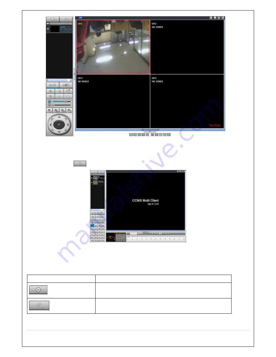
Click Search icon 

  to display the search screen.   


1. 

Dates with recorded data are displayed in different color. 

2. 

Select the date to search and click “PLAY” button to playback the video. 


8-5-2.  Main  Buttons  and  Description 

Button   

Description   

  Local playback 

To playback video stored in local PC. 

  Remote playback 

To playback video stored in a remotely connected DVR via network. 

Summary of Contents for CVN-0430F

Page 1: ......

Page 2: ...losion if battery is incorrectly replaced Replace only with the same or equivalent type recommended by the manufacturer Discard used batteries according to the manufacturer s instructions This symbol indicates the presence of important operating and maintenance servicing instructions in the literature accompanying the product This symbol indicates the presence of Uninsulated dangerous voltage with...

Page 3: ...power plug with wet hands Do not sit on Make sure the cables are connected properly Do not place heavy objects on connected units Never move this unit while the power is turned on Remove the power plug from the outlet when the unit is going to remain unused for long periods of time Do not block the cooling fans or air ducts Do not expose to extreme temperatures or humidity changes Warning Installa...

Page 4: ...urchase the unit Please check to ensure the components specified below are included NVR Unit Remocon Battery1 5V AAA x 2EA Quick User Guide Mouse Software Manual CD HDD Power SATA Cable HDD Bracket Screw Adapter DC12V 5A Power Cable 110V or 220V Adapter PoE DC48V 1A 2A Power Cable 220V Audio Cable Option ...

Page 5: ...emble HDD bracket with screws 2 Set the hole of bracket and case base then assemble with screws 3 Connect data cable and power cable Basic function of the MOUSE Left button SELECT function Wheel MOVEMENT function on a drop down menu ...

Page 6: ...ST1000VM002 fw SC12 1 TB SATA 3 5900 RPM 64 MB ST1000DM003 1 TB SATA 3 7200 RPM 64 MB ST31000524AS 1 TB SATA 3 7200 RPM 32 MB ST31000322CS 1 TB SATA 2 5900 RPM 8 MB ST31000526SV 1 TB SATA 3 7200 RPM 32 MB ST31000524AS 1 TB SATA 3 7200 RPM 32 MB ST31000340SV 1 TB SATA 2 7200 RPM 32 MB ST31000528AS 1 TB SATA 2 7200 RPM 32 MB ST1000VM002 1CT162 fw SC23 1 TB SATA 3 5900 RPM 64 MB ST3500312C8 500 GB SA...

Page 7: ...0EURS 63R8UYO 3 TB SATA 2 5400 RPM 64 MB WD30PURX 64P6ZY0 WD30EURX 64HYZY0 3 TB SATA 3 64 MB WD20PURX 64P6ZY0 WD20EURX 64HYZY0 2 TB SATA 3 64 MB WD20EURS 63SPKY0 2 TB SATA 2 5400 RPM 64 MB WD20EURX 63T0FY0 2 TB SATA 3 5400 RPM 64 MB WD20EARS 2 TB SATA 2 5900 RPM 64 MB WD20EARX 00PASB0 2 TB SATA 3 5900 RPM 65 MB WD20EADS 2 TB SATA 2 5400 RPM 32 MB WD20EURS 2 TB SATA 2 5400 RPM 64 MB WD10EZEX 00RKKA...

Page 8: ...SATA 3 WD2500AAKX 250 GB SATA 3 7200 RPM 16 MB WD2500AVVS 250 GB SATA 2 8 MB WD2500AAKS 250 GB SATA 2 7200 RPM 16 MB TOSHIBA TOSHIBA TOSHIBA TOSHIBA HDS723020BLE640 DT01ACA200 2 TB SATA 3 7200 RPM 64 MB DT01ABA200V 2 TB SATA 3 5700 RPM 32 MB NOTICE The brands and models of all HDD should be the same If the brands and models of each HDD are different with others the NVR may not recognize HDD ...

Page 9: ...rivate IP Camera Auto Connection 4 PoE 8 PoE 8 PoE LAN IP Camera Remote Access 10 100 Base T 10 100 1000 Base T Protocols TCP IP UDP DHCP HTTP NTP SMTP RTP RTSP ONVIF Live Frame Rate 120fps 240fps 480fps Recording Compression H 264 Baseline Main High Profile Resolution Frame Rate D1 120fps 240fps 480fps 720p 120fps 240fps 480fps 1080p 120fps 240fps 480fps Recording Mode Continuous Motion Sensor Sc...

Page 10: ... Internal Beep Yes Multi Language Yes e mail Notification Yes Network Access Mobile iPad iPhone Android Web Viewer Windows IE PC Client CCMS Remote Setup and Upgrade Yes Power Power Supply Voltage DC 12V 5A 48V 1A POE DC 12V 5A 48V 2A POE Temperature Operation Temperature 5 C 40 C During storage 10 C 50 C Weight Unit Weight Gross weight 4 1 Kgs 6 2 Kgs Dimension Unit Dimension W x H x D 380mm x 34...

Page 11: ...2 3 5 PoE Port SETUP 24 3 6 IP Camera SETUP through Web Viewer page 27 3 7 Dual Streaming 28 4 Setting up the NVR 28 4 1 Setup Main Live Screen 28 4 1 1 Setup MENU TREE 29 4 2 Setup IP CAMERA 31 4 2 1 SCAN Menu 32 4 2 2 ONVIF SETUP Menu 34 4 3 Setup DISPALY 35 4 4 Setup RECORD Mode 36 4 4 1 Recording Schedules 37 4 5 Setup DEVICE Mode 38 4 6 Setup STORAGE Mode 39 4 7 Setup SYSTEM Mode 41 4 8 Setup...

Page 12: ... 63 6 Back Up 64 6 1 Still Image backup onto USB flash Drive 64 6 2 Video backup 64 6 3 Transferring still images or video from the ARCHIVE list 65 6 4 Playback of Backup Video 66 7 Upgrading Firmware 67 7 1 Remote Firmware Upgrade 67 7 2 Firmware Upgrade at the DVR 69 8 CCMS Multi Client Multi Sites Monitoring Software 70 8 1 Overview 70 8 2 Recommended PC Hardware Specification 70 8 3 CCMS Insta...

Page 13: ...nd Disconnection 86 8 8 3 Still Image Capture 87 8 8 4 Live Display Record 88 8 8 5 Local playback and Remote playback 89 8 8 6 AVI Backup during Playback 91 9 CCMS Single Client 92 9 1 PC Specification 92 9 2 Installation 92 9 3 User s Guide 94 9 3 1 Live Display buttons and description 94 9 3 2 Site Addition 95 9 3 3 Site Connection 97 9 3 4 Site Search 97 9 3 5 Site Data Backup 98 9 3 6 Setup M...

Page 14: ...ts 10 100Mbps USB 2 0 port for video clip exporting and easy firmware upgrade via USB Flash Drive Exclusive File Format Backup and Player Variety of Ways Network Access via CMS Network Client Software Web Viewer and Mobile Viewer NOTE Under federal law The Fourth Amendment to the U S Constitution Title III of the Omnibus Crime Control and Safe Streets Act of 1968 as amended by the Electronic Commu...

Page 15: ...ve CD RW DVD RW BACK UP For still image back up in live display or search mode and video back up ESC Exit from the current menu SET UP To enter the main menu SEQ Channels in sequence Set to On in live display menu PTZ To control PTZ camera Channel selection 1ch 16ch Move upward in settings menu 1 For password input Move downward in settings menu 3 For password input Change value in settings menu 2...

Page 16: ...de or data back up 1 each on front and rear panel and a USB mouse can be connected OPEN CLOSE To eject or close CD DVD Drive optional 2 2 2 2 2 2 2 2 Rear Panel Figure 2 2 1 Connectors Ground Use for ground port PoE POWER DC48V input NV MP Series PoE PORT NV 04xxMP 4 Port PoE NV 0823 1643MP 8 Port PoE ETHERNET PORT2 Network Second Terminal No Internet access NV M Series without PoE Do not power th...

Page 17: ... RS 485 4 sensor inputs 1 alarm output and RS 485 for PTZ POWER DC12V input 2 2 2 2 3 3 3 3 Remote Control ID To set the remote control ID REC To start and stop manual recording SEARCH To go to SEARCH menu F ADV During playback To move the playback position 60 seconds forward During Pause To move the playback position moves 1 frame forward F REW During playback To move the playback position 60 sec...

Page 18: ...NVR ID number or use as number key 3 Initial Boot up Process 3 1 Initial Boot up and Basic Time Setup 1 During the first boot up the following logo will be displayed The background color on COMMAX while booting a system should be displayed differently with some Monitor 2 After the logo select the language and set date and time as specified below 3 2 Setting Daylight Saving Time To enable Daylight ...

Page 19: ...19 2 Go to SETUP SYSTEM DATE TIME SETUP 3 Select ON from the DAYLIGHT SAVING dropdown menu ...

Page 20: ...rd Time Daylight Saving Time AL Alabama GMT 6 GMT 5 AK Alaska GMT 9 GMT 8 AK Alaska Aleutian Islands GMT 10 NA AZ Arizona GMT 7 NA AZ Arizona Navajo GMT 7 GMT 6 AR Arkansas GMT 6 GMT 5 CA California GMT 8 GMT 7 CO Colorado GMT 7 GMT 6 CT Connecticut GMT 5 GMT 4 DC District of Columbia GMT 5 GMT 4 DE Delaware GMT 5 GMT 4 FL Florida GMT 5 GMT 4 ...

Page 21: ...MT 5 GMT 4 MI Michigan GMT 5 GMT 4 MI Michigan W GMT 6 GMT 5 MN Minnesota GMT 6 GMT 5 MS Mississippi GMT 6 GMT 5 MO Missouri GMT 6 GMT 5 MT Montana GMT 7 GMT 6 NE Nebraska GMT 6 GMT 5 NE Nebraska W GMT 7 GMT 6 NV Nevada GMT 8 GMT 7 NH New Hampshire GMT 5 GMT 4 NJ New Jersey GMT 5 GMT 4 NM New Mexico GMT 7 GMT 6 NY New York GMT 5 GMT 4 NC North Carolina GMT 5 GMT 4 ND North Dakota GMT 6 GMT 5 ND No...

Page 22: ... GMT 7 WV West Virginia GMT 5 GMT 4 WI Wisconsin GMT 6 GMT 5 WY Wyoming GMT 7 GMT 6 NOTE If you want the unit to automatically synchronize the local time the Time Zone must be properly set according to your local time zone 3 4 QUICK INSTALLATION Quick installation Menu for NVR and IP Camera Quick installation Right Click on the Main Screen Figure 3 4 Quick Installation Screen 3 4 1 Help user to se...

Page 23: ...n It will automatically setup the network for the system NVR Setup DDNS setting DDNS Dynamic Domain Name System allows a DNS name to be constantly synchronized with a dynamic IP address It allows using a dynamic IP address to be associated with a static domain name Refer to the full version manual for more information Click Finish to save the setup 3 4 2 Help user to setup IP Camera Setting 1 2 4 ...

Page 24: ...turer and then click on the scan button this will scan the networks for any cameras from the particular manufacturer Select on the desired Camera from the list and then check on register If necessary click on Preview to Preview the camera or Setup to change camera settings 3 5 PoE Port SETUP 1 2 3 4 ...

Page 25: ...25 Figure 3 5 1 PoE Port ...

Page 26: ...compression type of both Main and Sub stream must be H 264 Main 1920x1080 30fps 2 5Mbps 4CH Max throughput of the NVR is 20Mbps 8CH Max throughput of the NVR is 40Mbps Sub D1 30fps 1Mbps Audio G 711 Only G 711 is supported The NVR Series features a Plug and Play function with a PoE Switch The Plug and Play functionality requires the IP Camera to be in DHCP mode The NVR automatically assigns an IP ...

Page 27: ... 6 IP Camera SETUP through Web Viewer page NVR Series allows remote access to the IP Cameras through IP Camera Setup menu in Web Client Viewer Click the mouse right button Select IP Camera Setup Select Channel Number It lanuches the camera s own setup page In order for the web pages to launch from the IP Camera Setup menu when accessed from the WAN Ports 59011 to 59254 on the router must be port f...

Page 28: ...Stream is used by default when viewing through the network 4 Setting up the NVR The following sections detail the initial setup of the NVR Menu screen will close if user input is not received in 5 minutes 4 1 Setup Main Live Screen To enter the setup menu right click on the mouse and select setup from the submenu or press the setup button on the remote control Table 4 1 1 Live Screen and Quick Ope...

Page 29: ...d to assign a new password to protect the system User can assign a new password in SECURITY setup menu 4 1 1 Setup MENU TREE IP CAMERA CHANNEL VANDOR SCAN IP PORT WEB PORT PROTOCOL DISPLAY OSD OSD CONTRAST SEQUENCE SEQUENCE DWELL TIME CHANNEL NAME COVERT VIDEO OUTPUT RECORD CHANNEL RECORDING SENSOR RECORDING PRE RECORD POST EVENT RECORD AUDIO SCHEDULE DEVICE CHANNEL AUDIO SOURCE KEY TONE ...

Page 30: ...ME TIME DISPLAY FORMAT TIME ZONE DAYLIGHT SAVING SET DATE TIME CLIENT ACCESS NTP SEND EMAIL SYSTEM EVENT NOTIFICATION SECURITY USER AUTHENTICATION USER NAME USER PASSOWRD PLAYBACK AUTHORITY NETWORK LIVE AUTHORITY REMOTE PLAYBACK TIMEOUT NETWORK PORT NETWORK AUDIO PORT WEB PORT NETWORK TYPE DHCP STATIC IP SUBNET MASK GATEWAY DNS PRIMARY DNS SECONDARY DDNS OFF ...

Page 31: ...ACTORY DEFAULT SOFTWARE UPGRADE 4 2 Setup IP CAMERA Press the SETUP button and enter the password The setup menu is displayed as picture below Figure 4 2 IP Camera mode setup screen Table 4 2 Menu items in IP CAMERA mode setup Item Description CHANNEL To manually connect each camera click on the to get this window ...

Page 32: ...nd then Lon in box will be pop up Enter ID and Password of IP Camera VENDOR Select the Brand of the Camera SCAN Automatic IP Camera Search the network for IP Camera IP Enter the IP Address of the desired Camera PORT Enter the Camera stream Port Number default 554 WEB PORT Enter the Camera Web Port Number default 80 PROTOCOL Select a protocol TCP only NVR CH Select a NVR Display channel ID Enter th...

Page 33: ...the registration is completed the basic information is to be displayed Figure 4 2 1 2 IP CAMERA Setup Screen ONVIF The NVR Series can search for IP Cameras that are conformant to ONVIF Open Network Video Interface Forum In order to search for ONVIF Cameras the field associated with VENDOR has to be set to ONVIF Click on the Box associated with SCAN to scan the networks for ONVIF Conformance camera...

Page 34: ...ed If there is not one listed the ONVIF protocol of IP CAM is not compatible with NVR and therefore not supported Double click the listed profile to apply Enter ID and PASSWORD of IP CAM Registration is completed 4 2 2 ONVIF SETUP Menu Figure 4 2 2 1 ONVIF Setup Window Under ONVIF Setup the following can be viewed and changed VIDEO NETWORK SYSTEM settings Table 4 2 2 1 Menu Items in ONVIF Setup Sc...

Page 35: ...t the DISPLAY tab Then the DISPLAY menu is displayed as pictured below Navigate through the menu items using the mouse or the control button on the remote control and change the value of the menu item To return to the previous setup menu screen press the ESC button Figure 4 3 1 DISPLAY Setup Screen Table 4 3 1 Menu Items in DISPLAY Setup Screen Item Description OSD Enable disable on screen display...

Page 36: ...nel to apply the following settings using the mouse NAME Set the channel name Press the right square button and set the channel name and select OK using the mouse The name can be made up to 10 characters COVERT Enable disable display of the specified video channel in live display VIDEO OUTPUT Select 1280x720 or 1920x1080 4 4 Setup RECORD Mode In the SETUP menu select the RECORD tab Then the RECORD...

Page 37: ...the sensor setting for the selected channel PRE RECORD Enable disable pre event recording Pre event recording time is up to 20 minutes POST EVENT RECORD Set the post event recording time duration for the specified channel 10 30 seconds AUDIO Enable disable audio recording for the specified channel SCHEDULE Set the recording schedule 4 4 1 Recording Schedules To setup a recording schedule select SC...

Page 38: ...NSOR SENSOR recording Highlighted in Red CLEAR All of the selected channel recording setting is initialized COPY Schedule of the selected channel can be copied to other channels 4 5 Setup DEVICE Mode In the SETUP menu select the DEVICE tab Then the device menu is displayed as pictured below Navigate through the menu items using the mouse or the control button on the remote control and change the v...

Page 39: ...e REMOTE CONTROL ID Set the remote control ID 1 Select ID 2 Input the remote control ID number 3 An icon will indicate on the Live Screen if the remote control ID is synchronized The options are from 0 to 99 4 6 Setup STORAGE Mode In the SETUP menu select the STORAGE tab Then the STORAGE menu is displayed as pictured below Navigate through the menu items using the mouse or the control button on th...

Page 40: ...op once the hard drive is full DISK FORMAT Once clicked the user will have to confirm to format the Hard Drive After confirming the NVR will reboot and the format sequence will load The format sequence allows user to select which HDDs to format Caution It is recommended to archive any data that you may need in the future before formatting the hard drive DISK INFO Hard drive information Displays th...

Page 41: ... 4 7 1 SYSTEM Setup Screen Table 4 7 1 Menu Items in SYSTEM Setup Screen Item Description NVR ID NVR System ID Setup English and Numbers Only DESCRIPTION Press the button to view the system information Software Version Storage Size IP Address MAC Address and DDNS Status LANGUAGE Select the display language using the mouse or the remote control Once a language is selected the display language will ...

Page 42: ...g time EU Applies the EU daylight saving time Select the GMT AREA using the mouse or the control button Set the time difference with the standard time using the mouse or the button OTHERS If the time zone is neither USA nor EU set the date and time of the daylight saving period Select BEGIN or END using the control button and press the SEL button Caution Do not set the start time to 23 00 for DLS ...

Page 43: ...ust set the time manually SYSTEM TIME Mon Oct 10 13 46 49 2011 SERVER TIME Mon Oct 10 13 33 12 2011 NVR ID NVR IP ADDRESS 172 16 2 77 SEND EMAIL Enable disable the send e mail function ON OFF SERVER TYPE Select GMAIL HOTMAIL AOL YAHOO or MANUAL MAIL SERVER Enter the appropriate mail server information MAIL PORT Assign Mail Port number SECURE OPTION Select the secure mail server connection method S...

Page 44: ...l Beep and Alarm output Notification when the camera signal is lost HDD TEMPERATURE Enable Email Beep and Alarm output Notification when the HDD temperature HDD BAD SECTORS Enable Email Notification when the HDD has bad Sectors HDD ALMOST FULL Enable Email Notification when the HDD is almost full HDD FULL Enable Email Notification when the HDD is full HDD FAILURE Enable Email Beep and Alarm output...

Page 45: ...ss to Setup PB Enable Disable of access to Playback PTZ Enable Disable of access to PTZ Control REC OFF Enable Disable of manual Record NETWORK Enable Disable of access to Network Selected Checkbox The NVR will ask for a password when the given function is selected for all users Blank Checkbox The NVR will not ask for a password when the given function is selected for all users ADMIN USER1 USER2 U...

Page 46: ... confirm and select OK Then the message PASSWORD CHANGED is displayed The factory default password is 1111 It is highly recommended to assign a new password to protect the system PLAYBACK AUTHORITY Set authority level of playback on each user Checked box authorized to playback Blank check box no authority NETWORK LIVE AUTHORITY Live through Network access rights settings REMOTE PLAYBACK TIMEOUT Se...

Page 47: ...ol button on the remote control and change the value of the menu Figure 4 9 1 NETWORK Setup Screen Table 4 9 1 Menu Items in NETWORK Setup Screen Item Description PORT NVR port Default is 5445 NETWORK AUDIO PORT Set the port for sending audio data via network Default is 5446 and it has to be the next number of the NVR port PORT 1 WEB PORT Enter the port number for connection using web Default is 8...

Page 48: ...outer To access NVR beyond a router firewall you must open the proper TCP ports for live playback streaming for commands for remote backup and for audio streaming If these ports are not opened properly you can t access the NVR beyond a router o For live playback streaming for commands for remote backup Open the port number on NETWORK NETWORK PORT menu The default port number is 5445 o For bi direc...

Page 49: ...setting is the MAC address of the DVR 4 DDNS LOGIN ENABLED if User ID and password are available from completing the user registration at ddns commax com DIABLED if not registered as a user at ddns commax com and using HOST method to access the DVR connect to icommax net Access method Enter DDSN HOST NAME URL icommax net at the browser 5 Check whether the registered user ID and password for COMMAX...

Page 50: ...utes and DVR rebooting and when DDNS set 2 How to check the set DDNS status Click the System information tap at system menu or right mouse click A Ready communicating with set DDNS server B Not Ready Not communicating with set DDNS server Reason for Not Ready and how to check When the DVR is not connected to internet External server Check the server type whether Commax or the other Check the ID an...

Page 51: ... to the default settings The following settings such as Language NVR ID Security User Authentication Security User P W Date format DLS settings Network settings HDD overwrite Limit recording HDD serial number and HDD ERROR time will not be included LOAD FACTORY DEFAULT Press the button to reset the system to the factory default settings SOFTWARE UPGRADE Upgrade softeware to the latest version Afte...

Page 52: ... the current firmware version and the firmware version which you want to upgrade The system will upgrade automatically when pressing the upgrade button After upgrading the system should be restarted At that time the USB memory drive has to be pulled out on the system Figure 4 10 2 4 You could see the following warning message if you don t pull out the USB memory drive NOTICE 1 If selecting REBOOT ...

Page 53: ... remote setup menu 3 Go to the Remote Upgrade menu Then you can see the current F W version as follows To upgrade a new F W insert the F W in your PC and press the UPGRADE button 4 Then you can see the following progress bar and it would be taken around 150 seconds to upgrade ...

Page 54: ... the current F W version if the upgrade is succeeded 5 Live Search and Playback 5 1 Live View In the Live screen video inputs from the cameras are displayed as they are configured in the Display Setup screen Various on screen display OSD symbols which indicate the status of the DVR are described in Table 5 1 1 Figure 5 1 1 Live Viewing Screen ...

Page 55: ...t to enabled or disabled Click to enable and click again to disable Manual Record button or Emergency Record button If selected regardless of the settings the recording type is changed to continuous record and start recording all channels To disable click the icon once again ALARM OUT function On Off button An alarm is turned off during the alarm in progress Click to change the channel in split sc...

Page 56: ...e channels with audio input The channels with audio input will have the audio output Press AUDIO button on the front panel to set up the audio Event indicator by event such as motion detection video loss HDD failure S M A R T This icon indicates a network client is connected to the DVR This icon indicates the SEQUENCE mode is either enabled or disabled Continuous recording mode Manual recording Em...

Page 57: ...s and store as BMP files INSTANT PLAYBACK Live screen you can fast search Go Back to 10sec 20sec 30sec 60sec IP CAMERA INFORMATION Press the button to view the record setting of a selected channel SYSTEM INFORMATION Press the button to view the system information SYSTEM LOCK Locks the NVR from unauthorized user access SYSTEM SHUTDOWN Select this option to shutdown system 5 2 Digital Zoom in Live a...

Page 58: ...live screen Figure 5 3 1 Search Screen There are 7 ways of search menu such as Quick SEARCH TIME LINE Calendar EVENT GO TO FIRST TIME GO TO LAST TIME GO TO SPECIFIC TIME ARCHIVE LIST and LOG LIST on the screen 5 3 1 QUICK Search The Quick Search window is used to find stored video with ease using the thumb nail playback screen ...

Page 59: ...ecific date on a calendar 2 Select a channel from Channel Selection Screen Then 24 Hourly Thumbnail Search screen displays 3 Select the hourly thumbnail Then 60 Minute Thumbnail Search screen displays 4 Select the Minute thumbnail Then 2 Minute 30 Second Thumbnail Search screen displays 5 Select the Second thumbnail Then 10 Second Thumbnail Search screen displays ...

Page 60: ...e menu is selected the user can see a calendar which displays recorded dates with highlights Select a specific date and time Click and drag the red time indicator bar to the desired hour User can select specific minutes using a button in the above red box Press the PLAY button after selecting the specific time Press the PREV to return to the SEARCH window 5 3 3 Event Search The Event Search window...

Page 61: ...ton to save the data after selecting the specific data User can find a data of the specific channel and event using a button in the above red box as following Figure 5 3 3 2 Press the PREV to return to the SEARCH window Figure 5 3 3 2 Event Search Screen 5 3 4 Go To First Time You can access from the oldest recorded data on the NVR hard drive by selecting GO TO FIRST TIME on the SEARCH window Pres...

Page 62: ...d press the PLAY button after setting If there is no video data in the set date and time No Data Exist message displays 5 3 7 Archive List The ARCHIVE Search window is used to find previously stored video or images Figure 5 3 7 Archive Search Screen When the Archive menu is selected the user can see a calendar which has recording data Select a specific date and then the archived data will be displ...

Page 63: ...s again if a mouse pointer is positioned to the bottom of the screen Playback buttons and functions Return to the previous menu screen search window or exit from the Menu Press to fast forward the footage at 1x 2x and 4x speeds Playback speed is indicated as 1x 2x and 4x for normal twice and 4 times of the regular speed at the bottom right of the screen Normal 2x 4x Normal speed Press to rewind th...

Page 64: ...ont panel 1 In playback mode click on button or press Backup button on the front panel at the video scene that is to backup 2 Select STILL IMAGE NSF video in proprietary format AVI INTEGRATED SUBTITLE or AVI SEPARATED SUBTITLE MAC COMPATIBLE STILL IMAGE Still image in BMP format NSF Proprietary format that requires a proprietary player which is automatically included at the time of backup AVI INTE...

Page 65: ...to begin searching and navigate through the days using the mouse or the remote control 2 Once you have selected the date press the NEXT button to open the list of stored data 3 Use the mouse or the remote control to scroll through the archive list 4 Select a list of stored events in the archive list 5 Once the desired event has been selected press the DISPLAY button to view the still image or the ...

Page 66: ...mat NSF format video can be played back by the player the HD player that the NVR copies on USB flash drive with video Two folders are copied on USB flash drive BACKUP DATA NSF format video file and INDEX file for a title file of date and time HD PLAYER Exclusive video viewer ...

Page 67: ...at It can be played back without any player HD player is embedded to the EXE file Timestamp On AVI The subtitle is embedded to the video clip file The subtitle is embedded to the AVI file 7 Upgrading Firmware 7 1 Remote Firmware Upgrade Remote Firmware Upgrade is enabled via CCMS Single Multi or Web Viewer CCMS Single shown below ...

Page 68: ...he program to connect to the corresponding site 2 After connected click right mouse button to display the menu 3 Select Remote setup 4 A message window is displayed as shown below Enter the default password 1234 and click LOGIN 5 Click UPGRADE ...

Page 69: ...e in USB Memory Stick and download the firmware file in the upgrade folder The firmware name is in the following format main_xxxx_ 20130116 bin NOTICE upgrade folder must be created in the USB memory stick and copy the firmware file in the folder The USB memory stick should be inserted into USB port on the front or rear panel of the DVR 1 Enter SETUP menu 2 Select SOFTWARE UPGRADE in the CONFIG Se...

Page 70: ...gle screen Camera control and two way audio are enabled 8 2 Recommended PC Hardware Specification Minimum specification Recommended specification CPU Intel Pentium IV 2GHz Intel Core Quad CPU Q8400 2 66GHz Memory 512MB or higher 2GB or higher VGA 64MB or higher 512MB or higher Resolution 1024 768 1920 1200 Disk space 1GB 100GB OS Windows XP Vista Windows7 Windows 2008 32bit and 64bit Windows XP Vi...

Page 71: ...installation completed CCMS Multi Client icon is created on the Desktop of PC 8 4 Live monitoring Double click CCMS Multi Client icon to display the below main screen 8 4 1 Main screen 8 4 2 Buttons and description Button Description Local playback To playback video stored in local PC ...

Page 72: ... network connection Setup Enter setup menu of CCMS MULTI CLIENT Capture Still image capture Event log Log display of CCMS MULTI CLIENT connection and disconnection Pause Pause playback Alarm On Off the alarm of selected channel in CCMS MULTI CLIENT RECORD ON Store live display onto local PC AUDIO Volume control MIC Microphone volume control Camera control buttons PAN left right TILT up down ZOOM i...

Page 73: ... to COMMAX DDNS Server displays the registered Site Address and Port Number If invalid information entered Failed to connect message is displayed e Site name User defined settings f Site Address IP address of the device or the IP address searched from commax DDNS ex 172 161 1 78 g Port Number Default setting is 5445 2 Host method connection without registering as a member at ddns commax com a Ente...

Page 74: ...es with recorded data are displayed in different color 2 Select the date to search and click PLAY button to playback the video 8 5 2 Main Buttons and Description Button Description Local playback To playback video stored in local PC Remote playback To playback video stored in a remotely connected DVR via network ...

Page 75: ...ackup process of the data stored at the connected site End To set an end point of backup process of the data stored at the connected site BACKUP To backup the stored video AUDIO Volume control DVR SITE SPLIT To change the screen of selected site from 4 9 16 split display CHANNEL SPLIT To select main display settings Selected channel display Display of the recorded date information of the connected...

Page 76: ... function Save Path Browse to set the save path for data backup Miscellaneous Options Automatic reconnection To automatically reconnect when network disconnected Always On Top To set the program to be on top of other applications in display Time Format Select date format ex YYYY MM DD 8 6 2 EVENT Settings for event indication 8 6 2 1 Save path and size To set a save path and size of event ...

Page 77: ... date period 8 6 3 RECORD 8 6 3 1 Record Condition To set a local backup conditions and options of the recorded data at the site by event and channels 8 6 3 2 DISK To select a local drive to store the stored data at the site and to set storing size ...

Page 78: ...78 8 6 4 OSD To set the site information and event indication options 8 6 5 About version information Software version information is displayed ...

Page 79: ...elow menu Remote Setup By selecting Remote setup below menu is displayed CAUTION some of the functions settings are not enabled depending on the device at the site and its firmware version Change the settings in the menu displayed 8 7 1 DISPLAY Settings Change values for the live display 8 7 2 RECORD Settings Change values for RECORD menu ...

Page 80: ...80 8 7 3 DEVICE Settings Change setups for the PTZ camera control and the controller 8 7 4 STORAGE Settings Change setup values for STORAGE ...

Page 81: ...81 8 7 5 SYSTEM Settings Change setup values for SYSTEM 8 7 6 SECURITY Settings Change setup values for SECURITY ...

Page 82: ...82 8 7 7 NETWORK Settings Change setup values for NETWORK ...

Page 83: ...8 7 9 INFORMATION General information of the DVR connected via network 8 8 User Guide 8 8 1 Site Addition Deletion and Modify 8 8 1 1 Site Addition 1 Click the icon located on upper left of the screen The below menu is displayed ...

Page 84: ...mation entered Failed to connect message is displayed e Site name User defined settings f Site Address IP address of the device or the IP address searched from commax DDNS ex 172 161 1 78 g Port Number Default setting is 5445 3 Host method connection without registering as a member at ddns commax com a Enter the DDNS Host name registered at Site Address icommax net 예 Registered DDNS host name 0002...

Page 85: ...Click button to delete 8 8 1 3 Site Modify 1 Click the Net Finder icon to display the below menu 2 Select the site you wish to modify and click EDIT MODIFY 3 If registered as a member at ddns commax com a DDNS URL ID registered by user at ddns commax com for COMMAC DDNS Service ...

Page 86: ...searched from commax DDNS ex 172 161 1 78 g Port Number Default setting is 5445 4 Host method connection without registering as a member at ddns commax com a Enter the DDNS Host name registered at Site Address icommax net ex Registered DDNS host name 000269082d68 Enter 000269082d68 icommax net b Port Number Default setting is 5445 5 Account Account that was set at the DVR for network access ex adm...

Page 87: ...site or check the box at the top to select all 2 Click button to disconnect the selected site s 8 8 3 Still Image Capture A Double click on the channel that you wish to capture a still image of B Click capture button and below window is displayed ...

Page 88: ...88 C Set the Save Path File name and File Format and click OK to save 8 8 4 Live Display Record 1 Click the Setup button 2 Select Record menu 3 Select options and click OK to save ...

Page 89: ...8 5 Local playback and Remote playback 8 8 5 1 Playback videos stored in local PC 1 Click Local playback icon 2 Another local playback screen is displayed 3 As shown below drag the time line bar to the time you wish to playback from and click playback button 4 With mouse drag the time bar as shown below 5 Local playback screen ...

Page 90: ...ck button 2 Another remote playback screen is displayed 3 Select the site you wish to playback from and click Connect button 4 As shown below drag the time line bar to the time you wish to playback from and click playback button 5 Remote playback screen ...

Page 91: ...he time that you wish to backup from 3 Click the start point button to set the start time of backup 4 Drag the time line bar to the end point and click button to set the end time of backup The backup time period is indicated in green color as shown below 5 Click the backup button to view the backup time period in detail and modify if necessary ...

Page 92: ...ctions are allowed if enough network bandwidth is provided A single connection is highly recommended for reliable performance under low network bandwidth 9 1 PC Specification CPU Intel Pentium Ⅳ 1 4Ghz or higher Memory 512MB minimum 1GB or higher VGA memory 16MB minimum 64MB or higher Resolution 1024x768 O S Windows 2000 XP Professional XP home Direct X DirectX 8 1 or higher 9 2 Installation 1 Ins...

Page 93: ...93 3 Click Next button After installation is completed CCMS Client icon is placed on the Desktop of PC ...

Page 94: ...cording time of the data selected CONNECT DISCONNECT Connect Disconnect the site SEARCH After connection to the site is made click on the icon to enter Search menu DISPLAY MODE Select channel The selected channel is displayed PAN TILT ZOOM FOCUS Camera control PAN TILT ZOOM FOCUS CAPTURE Still image capture and save ...

Page 95: ...y Live Display still image capture The still image capture of live display is saved in BMP or JPEG format 1 Click the channel to capture The border line of the channel is indicated in red color 2 Click the capture button to display the menu 3 Setup the save path and file name and click OK to save 9 3 2 Site Addition 1 Click the Setup button to display the menu as shown below 2 Click Site to displa...

Page 96: ...red Site Address and Port Number If invalid information entered Failed to connect message is displayed e Site name User defined settings f Site Address IP address of the device or the IP address searched from commax DDNS ex 172 161 1 78 g Port Number Default setting is 5445 2 Host method connection without registering as a member at ddns commax com a Enter the DDNS Host name registered at Site Add...

Page 97: ...splay the site registered and click OK to make connection 9 3 4 Site Search Click Search button to enter Search menu Search menu icons and description Button Function Description DATE TIME Search date and time are displayed DISCONNECT Disconnect the sie ...

Page 98: ... Channel select and Quad display buttons Search method 1 Select the date you wish to search from the calendar Dates with recorded data are indicated in blue 2 As the date is selected the recorded data at the bottom of the screen will be indicated in blue 3 Select the specific time that you wish to search from and click PLAY button 9 3 5 Site Data Backup 1 Click the Mark in button and move the time...

Page 99: ...d as above and click Backup icon to display below AVI Backup menu 3 Set the save path and click OK proceed with backup The backup file can be played via general media players that support AVI format 9 3 6 Setup Menu and Description Click Setup button and below menu is displayed ...

Page 100: ...wse to set the save path for data backup Miscellaneous Options Display network status To display the network status of the connected site Automatic reconnection To automatically reconnect when network disconnected Time Format Select date format ex YYYY MM DD SITE Site Add Delete Modify ...

Page 101: ...101 EVENT To select event to record LOG EVENT Search Search recorded event ...

Page 102: ...back up and save to local PC Record Condition To set a local backup conditions by Always Event Auto record options Event To select backup option by Motion and Alarm Channes Select channels to backup Record Disk Set the Drive and space ...

Page 103: ...e local PC for backup Disk Info HDD information of the local PC Disk full Select overwrite option to be enabled disabled when disk is full Language Setup language the user wishes to use About The version information of CCMS Single is displayed ...

Page 104: ...u and Description After connecting to the site click right mouse button to display the menu shown below Click Remote setup to display the below WEB SETUP screen Enter the default password 1234 1 Remote setup for DISPLAY Settings ...

Page 105: ...105 APPLY Enter or modify the values and click APPLY to save and apply RELOAD Return to previous settings 2 Remote setup for RECORD Settings 3 Remote setup for DEVICE Settings ...

Page 106: ...106 4 Remote setup for STORAGE Settings 5 Remote setup for SYSTEM Settings ...

Page 107: ...107 6 Remote setup forSECURITY Settings 7 Remote setup for NETWORK Settings ...

Page 108: ...he router or hub 1 Connect DVR and network switch or hub or router with LAN cable CAT 5 2 Press SETUP button on the front panel of DVR and check the IP address of the DVR located at SETUP SYSTEM SYSTEM INFO 3 In the settings of the router use the Port Forwarding menu and open TCP port 5445 5446 and 80 WEB ...

Page 109: ...SS 2 Execute the Network Client Program and click Site Addition button to register the site 3 Click Connect button to open the menu and enter Site Name Site Address Port Number ID and Password Click OK to connect B 2 Remote Connection to DVR in WAN environment via DDNS Service 1 Open TCP port of the router default port 5445 Please refer to 10 A ...

Page 110: ...mmax net in the web browser ex Registered DDNS host name 000269082d68 Enter 000269082d68 icommax net B As the connection of the corresponding DVR is made click Connect on the upper right corner of the screen C IP Address Check whether the same URL is displayed as the URL entered in the web browser D ID Password Enter ID ADMIN or USER1_ and password of the account that has access to the DVR Default...

Page 111: ...er at ddns commax com A Connect to http ddns commax com and enter the pre registered ID and Password to login The ID and Password must match the ID and Password of the user registered in the DVR B Click PreDDNS in DDNS Service menu ...

Page 112: ...VR in WAN ⓓ ID URL URL for COMMAX DDNS Service Default http ddns commax com MAC address of the DVR Previous COMMAX DDNS Service activation http ddns commax com User defined ID ⓔ State DDNS status of DVR ON DVR s setup is set as COMMAX DDNS possible to use DDNS service Off DVR s setup is not set as COMMAX DDNS not possible to use DDNS service ⓕ Enrol To activate the selected DVR for COMMAX DDNS ser...

Page 113: ...mber are displayed Then enter the user ID and Password to connect 11 Web Client Web Viewer The Web Client enables a user to connect to the site via network without installing a client software 1 First check the DVR s IP address in SETUP SYSTEM SYSTEM INFO 2 Enter the DVR s IP address or the registered COMMAX DDNS URL in the web browser 3 If connected for the first time below ActiveX control instal...

Page 114: ...stered by user at ddns commax com for COMMAC DDNS Service ex http ddns commax com CVD 9616H_DVR ID registered by user CVD 9616H_DVR b DDNS ID Registered account at COMMAX DDNS Server email type c DDNS Password The password registered at COMMAX DDNS d Search Entering the above DDNS URL DDNS ID and DDNS Password to connect to COMMAX DDNS Server displays the registered Site Address and Port Number ...

Page 115: ...ed DDNS host name 000269082d68 Enter 000269082d68 icommax net b Port Number Default setting is 5445 3 Account Account that was set at the DVR for network access ex admin or user1 4 Password Enter the password for the corresponding account default password 1234 5 Click OK button to create the list Select the site you wish to connect from the list and click CONNECT button 7 Web Client screenshot Ple...

Page 116: ...evice List a Site Enter the Site name b IP Registered DVR Host name icommax net ex 000269082d68 icommax net c Port Enter Port Number Default 5445 7 icommax net 을 이용한 호스방식 접속 7 Host method connection via icommax net 8 If registered as a member at ddns commax com ...

Page 117: ...and Save 10 Confirm DVR information is correct and touch Save c Check IP Port values match the registered information at ddns commax com 11 Touch the site to view from the list 13 Screenshot of CMVS DDNS registration item description a URL User defined ID that is registered at the Commax DDNS Server b DDNS ID User ID in email type registered at the COMMAX DDNS Server ...

Page 118: ...t setting is 5445 ID The user account registered at the DVR for network access ex admin Password The above user password of the DVR default setting is 1234 If you select a single channel from Quad mode you can zoom in and out by using two fingers Android phones CMVS installation and instruction 1 Touch Play Store 2 Touch Search icon 3 Search for CMVS or COMMAX 4 Touch CMVS 5 Install CMVS 6 Execute...

Page 119: ...If registered as a member at ddns commax com a Check the box next to Commax DDNS b Enter information registered at Commax DDNS Server Device ID ID registered by user at ddns commax com for Commax DDNS Service ex http ddns commax com CVD 9616H_DVR User registered ID CVD 9616H_DVR DDNS ID Registered account at COMMAX DDNS Server email type DDNS Password The password registered at COMMAX DDNS Server ...

Page 120: ...l time Monitoring a Select a registered site b In monitoring mode select Real time monitoring c Select a channel you wish to view d Touch Real time Monitoring e Touch the right or left arrow to view either the previous or next channel ...

Page 121: ...121 13 View the registered sites Playback a Select a site you wish to view b Select Playback c Select date and time and touch OK d Playback of the recorded video starts ...

Page 122: ...122 ...

Reviews: