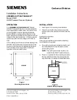
Press “NONE” to access the submenu used to select the output type.
17/06/2020 14:06
NONE
Periphery
Loop
Network
Action
Event
Description of the available Output types:
◊
NONE
: the output is not used.
◊
PERIPHERY
: select this option when the output to be activated is a periphery device relay built into the panel.
◊
LOOP
: select this option when the output to be activated belongs to an output module (modules 41IOM004, 41IOM022,
41IOM122, 41IOM000, 41IOM000/240).
◊
NETWORK
: select this option when the output should be activated by an event / device belonging to another panel
connected to its network (RS485 / LAN).
◊
ACTION
: select this option when the output should be activated by an “action” that has taken place.
◊
EVENT
: select this option when the output should be activated by a “general event”.
Description of the Outputs menu buttons:
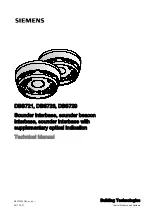
Once the desired output type has been selected, you need to set the parameters relating to that specific output; the general
screen with parameters common to all outputs is shown below:
17/06/2020 14:06
SAVE
Output Number
Name
Unlatched
Behaviour
NORMAL
Output polarity
0
Delay
CONTINUOUS
Output pulse type
Loop
Type
1
More
Edit Outputs Map
• Output Number: use the + & - buttons or enter the number directly to select an output between 1 and 250. The screen
content may vary depending on the settings for the selected output Type. All outputs are pre-set to NONE by default.
• Name: field used to enter a name or description for the output being programmed.
• Behaviour: field used to enter the output behaviour type:
◊ Auto Reset – the output status remains enabled until the event that generated it is disabled
◊ Manual Reset – the output is only disabled after a Reset event
• Polarity: field used to enter the output polarity:
◊ Normal – the output is Enabled when the result of the logic function is TRUE
◊ Inverted – the output is Enabled when the result of the logic function is FALSE
• Output Delay: a delay can be set for output enabling, between 0-600 seconds.
60