Removal and replacement of ADU modules
8-66
Chapter 8: Service & maintenance
98-133966-G1
8. Remove the Elevation Drive Belt.
8.5.9.4
Inserting a new Elevation Drive Belt
To insert a new Elevation Belt follow the instructions above in reverse
order — while observing the following guidelines:
Inserting a new Elevation Motor and
8.5.9.5
Removing the Azimuth Drive Belt
1. Open the service hatch by releasing the two latches with Torx
screws.
2. Switch off the power to the antenna on the service switch.
3. Rotate the antenna pedestal so that the arm with the GPS module
faces the service hatch and
4. Rotate the Antenna Dish to top position.
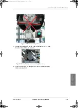
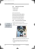
Figure 8-87: Elevation Drive Belt
Tools needed:
• 4 x 150 mm Allen key
(located inside the service
door of the ADU)
• Acoustic frequency meter
SAILOR900TM.book Page 66 Monday, September 16, 2013 11:01 AM
Summary of Contents for Sailor 900 VSAT
Page 2: ...98 138976 A Cover_SAILOR 900 VSAT System_407090B indd 2 15 04 2013 15 54 39 ...
Page 28: ...List of tables xxvi 98 133966 G1 SAILOR900TM book Page xxvi Monday September 16 2013 11 01 AM ...
Page 257: ...Appendices SAILOR900TM book Page 1 Monday September 16 2013 11 01 AM ...
Page 258: ...SAILOR900TM book Page 2 Monday September 16 2013 11 01 AM ...
Page 355: ...98 138976 A Cover_SAILOR 900 VSAT System_407090B indd 3 15 04 2013 15 54 40 ...


