background image


Chapter 3      Installing the Router

Connecting to the Console and Auxiliary Ports

3-18

Cisco 12006 and Cisco 12406 Router Installation and Configuration Guide

OL-11497-03

PRP Console and Auxiliary Ports

The system console port on the PRP is a DCE RJ-45 receptacle for connecting a 
data terminal, which you must configure. The console port is labeled 

Console

, as 

shown in 

Figure 3-9

. Before connecting the console port, check the 

documentation for your terminal to determine the baud rate. 

If your documentation does not specify settings, use the following terminal 
settings: 9600 baud, 8 data bits, no parity, and 2 stop bits. The console port 
requires a rollover RJ-45 cable.

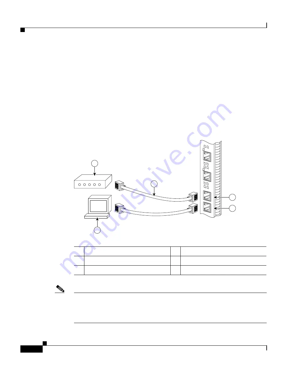
Figure 3-9

PRP Console and Auxiliary Port Connections

Note

The console and auxiliary ports are both asynchronous serial ports; any devices 
connected to these ports must be capable of asynchronous transmission. 
Asynchronous is the most common type of serial device; for example, most 
modems are asynchronous devices.

1

Modem

4

Auxiliary port

2

Console terminal

5

Console port

3

RJ-45 Ethernet cables

70692

RX

TX

PRIMAR

Y

SLO

T-

1

SLO

T-

0

LINK

EN

RX

TX

ETH 1

ETH 0

A

UX

CONSOLE

LINK

PRIMAR

Y

EN

1

3

4

5

2

Summary of Contents for 12006 series

Page 1: ...ystems Inc 170 West Tasman Drive San Jose CA 95134 1706 USA http www cisco com Tel 408 526 4000 800 553 NETS 6387 Fax 408 527 0883 Cisco 12006 and Cisco 12406 Router Installation and Configuration Guide Text Part Number OL 11497 03 ...

Page 2: ...auses interference to radio or television reception try to correct the interference by using one or more of the following measures Turn the television or radio antenna until the interference stops Move the equipment to one side or the other of the television or radio Move the equipment farther away from the television or radio Plug the equipment into an outlet that is on a different circuit from t...

Page 3: ... Any Internet Protocol IP addresses used in this document are not intended to be actual addresses Any examples command display output and figures included in the document are shown for illustrative purposes only Any use of actual IP addresses in illustrative content is unintentional and coincidental Cisco 12006 and Cisco 12406 Router Installation and Configuration Guide 2009 Cisco Systems Inc All ...

Page 4: ......

Page 5: ...ation xvii Documentation Feedback xvii Cisco Product Security Overview xviii Reporting Security Problems in Cisco Products xix Obtaining Technical Assistance xix Cisco Technical Support and Documentation Website xx Submitting a Service Request xx Definitions of Service Request Severity xxi Obtaining Additional Publications and Information xxii C H A P T E R 1 Product Overview 1 1 Introduction 1 1 ...

Page 6: ...ic Switching Capacity and Router Type 1 12 Switch Fabric Redundancy 1 12 Maintenance Bus 1 13 Power Up Down Control 1 13 Device Discovery 1 13 Code Download 1 14 Diagnostics 1 14 Environmental Monitoring and Alarms 1 14 Route Processors 1 15 Route Processor Functions 1 15 Route Processor Types 1 16 Gigabit Route Processor 1 16 GRP Memory Components 1 19 System Status LEDs 1 21 Soft Reset Switch 1 ...

Page 7: ...larm Card Status 1 36 Power Source Monitoring 1 37 Alarm Relay Contact Connector 1 37 Power Subsystems 1 37 AC Power Subsystem 1 38 AC PDU 1 38 AC Input Power Supply 1 40 DC Power Subsystem 1 42 DC PDU 1 42 DC Input Power Entry Module 1 44 Power Distribution 1 47 Blower Module 1 47 Air Filters 1 49 Cable Management System 1 50 Field Replaceable Units 1 52 Technical Specifications 1 52 C H A P T E ...

Page 8: ...es 2 10 Types of Equipment Racks 2 10 Equipment Dimensions and Site Layout 2 11 Ventilation 2 13 Power Connection Guidelines 2 14 Power Connection Guidelines for AC Powered Routers 2 14 Power Connection Guidelines for DC Powered Routers 2 16 Grounding Connections 2 16 Site Wiring 2 20 Electromagnetic Interference 2 20 Distance Limitations 2 20 Unpacking and Repacking the Router 2 21 Site Preparati...

Page 9: ...liary Ports 3 14 GRP Console Port Signals 3 16 GRP Auxiliary Port Signals 3 16 PRP Console and Auxiliary Ports 3 18 PRP Console Port Signals 3 19 PRP Auxiliary Port Signals 3 20 Installing a Flash Memory Card 3 20 Connecting the GRP to an Ethernet Network 3 22 Connecting the PRP to an Ethernet Network 3 25 PRP Ethernet Connections 3 27 Connecting to an AC Power Source 3 29 Connecting to a DC Power...

Page 10: ... Interface 3 50 User Interface Command Modes 3 50 User EXEC Mode 3 51 Privileged EXEC Mode 3 51 Global Configuration Mode 3 52 Interface Configuration Mode 3 52 Subinterface Configuration Mode 3 52 ROM Monitor Mode 3 52 Configuration Changes 3 53 setup Command Interactive Script Example 3 54 Configuring Global Parameters 3 57 Host Name 3 57 Passwords 3 57 Protocols 3 58 Configuring Network Interfa...

Page 11: ...Memory 3 72 Copying Files 3 72 Copying a Cisco IOS Software Image 3 74 Copying Cisco IOS Software Updates 3 75 Copying Files Between RP Memory and a Flash Memory Card 3 77 Copying Configuration Files from RP NVRAM to a Flash Memory Card 3 77 Copying a Configuration File from RP DRAM to a Flash Memory Card 3 80 Copying a Configuration File from a Flash Memory Card to RP NVRAM 3 81 Locked Blocks in ...

Page 12: ... Troubleshooting the AC Input Power Subsystem 4 23 Troubleshooting the DC Input Power Entry Module 4 26 Troubleshooting the Processor Subsystem 4 28 Troubleshooting the RP 4 28 Troubleshooting the Line Cards 4 31 Troubleshooting by Using the Alarm Cards 4 33 Monitoring Alarm Card Status 4 33 Monitoring Switch Fabric Status 4 33 Monitoring Critical Major and Minor Alarm Status 4 34 Troubleshooting ...

Page 13: ...er Module 6 9 Troubleshooting the Blower Installation 6 12 Removing and Replacing AC and DC Power Subsystem Components 6 13 Installation Guidelines 6 14 Power Supply and PDU Compatibility 6 14 Installing Upgrade Kits 6 17 Removing and Replacing an AC PEM 6 18 Troubleshooting the AC Power Supply Installation 6 22 Removing and Replacing an AC PDU 6 24 Removing and Replacing a DC PEM 6 31 Troubleshoo...

Page 14: ...g a Switch Fabric Card 6 63 Verifying the Installation of the Switch Fabric Card 6 64 Removing and Installing an Alarm Card 6 65 Removing an Alarm Card 6 66 Installing an Alarm Card 6 66 Verifying the Installation of the Alarm Card 6 67 Removing and Installing the Chassis 6 68 Tools and Equipment 6 68 Before You Begin 6 69 Preparing the Replacement Chassis 6 69 Preparing the Defective Chassis 6 70...

Page 15: ...n a Tabletop or Flat Surface 6 75 Installing the Chassis in the Equipment Rack 6 76 Reattaching the Supplemental Bonding and Grounding Cable 6 76 Reconnecting Cables to the Replacement Chassis 6 76 Reconnecting RP Cables 6 76 Reconnecting Alarm Cards Cables 6 76 Reconnecting Line Card Network Interface Cables 6 77 Reconnecting Power to the Router 6 77 Installing the Blower Module 6 77 Restarting t...

Page 16: ...Contents 14 Cisco 12006 and Cisco 12406 Router Installation and Configuration Guide OL 11497 03 ...

Page 17: ...nic circuitry and wiring practices and have experience as an electronic or electromechanical technician Purpose This installation and configuration guide contains procedures for installing the router hardware creating a basic startup configuration file and powering on the router for the first time Organization The Cisco 12006 and Cisco 12406 Router Installation and Configuration Guide contains the...

Page 18: ...s Router Describes how to load and run the field diagnostics for the Cisco 12000 Series Internet Router Chapter 6 Maintaining the Router Explains safety at the field replaceable unit FRU level removal and replacement procedures for field replaceable units and assemblies and associated procedures to troubleshoot and verify FRU and device operation Chapter A Technical Specifications Provides the tec...

Page 19: ... sample console screen displays are in screen font Information you enter is in boldface screen font Nonprinting characters such as passwords are in angle brackets Default responses to system prompts are in square brackets Exclamation points at the beginning of a line indicate a comment line Caution Means reader be careful You are capable of doing something that might result in equipment damage or ...

Page 20: ...L http www cisco com You can access international Cisco websites at this URL http www cisco com public countries_languages shtml Product Documentation DVD Cisco documentation and additional literature are available in the Product Documentation DVD package which may have shipped with your product The Product Documentation DVD is updated regularly and may be more current than printed documentation T...

Page 21: ... this URL http www cisco com go marketplace Cisco will continue to support documentation orders using the Ordering tool Registered Cisco com users Cisco direct customers can order documentation from the Ordering tool http www cisco com en US partner ordering Instructions for ordering documentation using the Ordering tool are at this URL http www cisco com univercd cc td doc es_inpck pdi htm Nonreg...

Page 22: ...ility Policy portal at this URL http www cisco com en US products products_security_vulnerability_policy ht ml From this site you can perform these tasks Report security vulnerabilities in Cisco products Obtain assistance with security incidents that involve Cisco products Register to receive security information from Cisco A current list of security advisories and notices for Cisco products is av...

Page 23: ... reach PSIRT by telephone 1 877 228 7302 1 408 525 6532 Tip We encourage you to use Pretty Good Privacy PGP or a compatible product to encrypt any sensitive information that you send to Cisco PSIRT can work from encrypted information that is compatible with PGP versions 2 x through 8 x Never use a revoked or an expired encryption key The correct public key to use in your correspondence with PSIRT ...

Page 24: ...o locate your product serial number before submitting a web or phone request for service You can access the CPI tool from the Cisco Technical Support Documentation website by clicking the Tools Resources link under Documentation Tools Choose Cisco Product Identification Tool from the Alphabetical Index drop down list or click the Cisco Product Identification Tool link under Alerts RMAs The CPI too...

Page 25: ...RL http www cisco com techsupport contacts Definitions of Service Request Severity To ensure that all service requests are reported in a standard format Cisco has established severity definitions Severity 1 S1 Your network is down or there is a critical impact to your business operations You and Cisco will commit all necessary resources around the clock to resolve the situation Severity 2 S2 Opera...

Page 26: ...zing Internet and networking investments Each quarter Packet delivers coverage of the latest industry trends technology breakthroughs and Cisco products and solutions as well as network deployment and troubleshooting tips configuration examples customer case studies certification and training information and links to scores of in depth online resources You can access Packet magazine at this URL ht...

Page 27: ...ts offered by Cisco Systems as well as customer support services can be obtained at this URL http www cisco com en US products index html Networking Professionals Connection is an interactive website for networking professionals to share questions suggestions and information about networking products and technologies with Cisco experts and other networking professionals Join a discussion at this U...

Page 28: ...xxiv Cisco 12006 and Cisco 12406 Router Installation and Configuration Guide OL 11497 03 ...

Page 29: ...nd functional descriptions of the hardware related features Introduction The routers described in this guide are part of the Cisco 12006 and Cisco 12406 series routers and include The original Cisco 12006 and Cisco 12406 series routers The Cisco 12006 and Cisco 12406 enhanced series routers The enhanced series of routers use higher capacity power supplies a more powerful blower module and have a n...

Page 30: ...s switch fabric Other than their various capacities these routers are almost identical Differences between each router are described unless otherwise noted all information in this publication applies to all routers Product Description The Cisco 12006 and Cisco 12406 routers shown in Figure 1 1 are members of the Cisco 12000 series router family These routers are aimed at scaling the Internet and e...

Page 31: ...15 m equipment rack Cisco 12006 and Cisco 12406 routers support system software downloads for most Cisco IOS software upgrades which enables you to remotely download store and boot from a new Cisco IOS image 1 Line card slots five 5 Alarm card slots two 2 RP slot 6 Power module bays two 3 Blower module 7 CSC slots two 4 SFC slots three 8 Cable management bracket 101344 SL OT 0 GIGABIT ROUTE PROCES...

Page 32: ...e slots for CSCs three dedicated hot swappable slots for SFCs Note The Cisco 12006 Router uses 2 5 Gbps switch fabric the Cisco 12406 Router uses 10 Gbps switch fabric You cannot mix 2 5 Gbps switch fabric cards and 10 Gbps switch fabric cards in a chassis The router will not operate with a mix of switch fabric card types Note When operating your router with a single CSC the second CSC slot must h...

Page 33: ...bility structural and electronics compliance Electromagnetic Compatibility and Electrostatic Discharge Compliant Cisco 12006 and Cisco 12406 routers comply with emissions immunity and electrostatic discharge ESD standards for both product and packaging Bonding and Grounding Bonding and grounding for safety circuit protection noise currents reliability and operations compliance Environmental Monito...

Page 34: ...er cable management with support for high density fiber Fast Ethernet FE ports Current 1 275 inch pitch line cards will fit in the line card cage with the addition of a front panel adapter cover The line card adapter cover is included with the 1 275 inch line card 1 Blower module 4 Air exhaust vents 2 Blower module LEDs 5 PDU behind Blower module AC PDU shown 3 Blower module handle 101114 HIGH SPE...

Page 35: ... page 1 49 Cable Management System page 1 50 Chassis The Cisco 12006 and Cisco 12406 router chassis is an enclosure that consists of two integral card cages and two power module bays see Figure 1 1 RP and Line Card Slots The RP and line card cage has six user configurable slots that support one RP and up to five line cards Network interfaces reside on the line cards that connect the switch fabric ...

Page 36: ...nder the CSC slots See Figure 1 1 For more information about the role of the alarm cards see the Alarm Cards section on page 1 35 Note The two alarm cards occupy slots under the two CSC slots in the CSC card cage but are not part of the switch fabric Chassis Backplane All of the card cages are tied together electrically through a passive system backplane in the back of the chassis Nearly all of th...

Page 37: ...stems section on page 1 37 Caution To ensure that the chassis configuration complies with the required power budgets use the on line power calculator Failure to properly verify the configuration may result in an unpredictable state if one of the power units fails Contact your local sales representative for assistance Cooling Cisco 12006 and Cisco 12406 routers are equipped with a blower module to ...

Page 38: ...tch Fabric Card Types The CSCs are installed in the half width slots labeled CSC 0 and CSC 1 on the lower left side of the chassis located directly beneath the RP and line card cage and directly above the alarm card bays The three SFCs are installed in the half width slots labeled SFC 0 SFC 1 and SFC 2 on the lower right side of the chassis Note To operate Cisco 12006 and Cisco 12406 routers must ...

Page 39: ...ing information and system clock information from the CSC The SFC contains only the switch fabric circuitry which carries user traffic between line cards or between the RP and the line cards The SFC receives scheduling information and the system clock sent from the CSC Nonredundant and Redundant System Configurations Cisco 12006 and Cisco 12406 routers are available in two system configurations 1 ...

Page 40: ...2406 Router is based on a 10 Gbps switch fabric where each CSC or SFC provides a 10 Gbps full duplex connection to each line card in the system The 10 Gbps switch fabric consists of the Clock and Scheduler Card product number GSR6 CSC and the Switch Fabric Card product number GSR6 SFC The 10 Gbps switch fabric cards are labeled simply CSC and SFC Note You cannot mix 2 5 Gbps switch fabric cards an...

Page 41: ...t component device discovery code download diagnostics and environmental monitoring and alarms Power Up Down Control Each MBus module directly controls the DC DC converters on the component on which it is mounted based on commands the component receives from its on board EPROM and from the RP Each MBus module is tied directly to DC voltage from the alarm card When power is applied to the router al...

Page 42: ...e Environmental Monitoring and Alarms The MBus module on each component monitors the environment of that component as follows Line cards and the RP are monitored for temperature by two temperature sensors mounted on each card The MBus module makes voltage adjustments through software for the 2 5 VDC 3 3 VDC and 5 VDC DC DC converters Clock and scheduler cards and switch fabric cards are monitored ...

Page 43: ...ry port for other external equipment such as modems Providing an IEEE 802 3 10 100 megabit per second Mbps Ethernet port for Telnet functionality Running routing protocols Building and distributing routing tables to the line cards Providing general system maintenance functions for the router The RP will function in any slot in the line card RP card cage but slot 5 is the recommended slot If the ro...

Page 44: ...cy the second RP must be of the same type as the primary RP Gigabit Route Processor This section provides information about the GRP The GRP front view is shown in Figure 1 4 Figure 1 4 Gigabit Route Processor Front View The GRP card has the following components RISC processor IDT R5000 Reduced Instruction Set Computing RISC processor used for the CPU The CPU runs at an external bus clock speed of ...

Page 45: ... Flash disks The GRP is shipped with 20 MB of Flash memory as the default configuration Sensors Air temperature sensors for environmental monitoring Note The GRP memory options and instructions for upgrading memory are described in the Cisco 12000 Series Gigabit Switch Router Memory Replacement Instructions Document Number 78 4338 xx The Cisco IOS software images for operating the router reside in...

Page 46: ...de OL 11497 03 Figure 1 5 GRP Layout Backplane connector SLOT 0 GIGABIT ROUTE PROCESSOR SLOT 1 CO LL LIN K TX RX RJ 4 5 M II RESET AUX EJECT H10547 Bank 2 DRAM DIMMs Bank 1 PCMCIA slots slot 0 bottom slot 1 top Console port Ethernet interface RJ 45 or MII Alphanumeric LED displays Auxiliary port Flash SIMM U17 U42 U39 ...

Page 47: ... the GRP 1 or 2 64 MB or 128 MB DIMMs based on DRAM required for main Cisco IOS software functions U39 bank 1 U42 bank 2 SRAM 512 KB fixed 2 2 This memory is neither user configurable nor field upgradeable Secondary CPU cache memory functions NVRAM 512 KB fixed 2 System configuration files register settings and logs Flash Memory 8 MB SIMM3 3 SIMM socket is wired according to a Cisco design and doe...

Page 48: ...oftware register settings and environmental monitoring logs This information is backed up with built in lithium batteries that retain the contents for a minimum of five years NVRAM is not user configurable and cannot be upgraded in the field Flash Memory Flash memory allows you to remotely load and store multiple Cisco IOS software and microcode images You can download a new image over the network...

Page 49: ...ctivity LEDs labeled SLOT 0 and SLOT 1 one LED per Flash memory slot Turns on when the slot is accessed Four RJ 45 Ethernet port activity LEDs labeled LINK COLL TX and RX These LEDs are used only by the RJ 45 Ethernet connector and are disabled when the media independent interface MII Ethernet port is in use The LEDs indicate link activity LINK collision detection COLL data transmission TX and dat...

Page 50: ...o IOS software The alphanumeric LED message displays also provide information about different levels of system operation including the following Status of the GRP Router error messages User defined status and error messages Note A complete descriptive list of all system and error messages is located in the Cisco IOS System Error Messages publications Soft Reset Switch The soft reset switch see Fig...

Page 51: ...ning in the GRP faceplate To press the switch you must insert a paper clip or similar small pointed object into the opening PCMCIA Slots The GRP has two PCMCIA slots Either slot can support a Flash memory card or an input output I O device as long as the device requires only 5 2 VDC The GRP supports only Type I and Type II devices It does not support 3 3 VDC PCMCIA devices Each PCMCIA slot has a b...

Page 52: ...wing two port connection types RJ 45 receptacle An 8 pin media dependent interface MDI RJ 45 receptacle for either an IEEE 802 3 10BASE T 10 Mbps or an IEEE 802 3u 100BASE TX 100 Mbps connection MII receptacle A 40 pin media independent interface MII receptacle that provides additional flexibility in Ethernet connections Note The RJ 45 and MII receptacles on the GRP represent two physical connecti...

Page 53: ... PRP contains the following components PowerPC processor Motorola PowerPC 7450 CPU which runs at an external bus clock speed of 133 MHz and an internal clock speed of 667 MHz SDRAM Up to 2 GB of Cisco approved SDRAM on two DIMMs 512 MB of SDRAM is the default shipping configuration SDRAM is field replaceable only when using Cisco approved DIMMs SRAM 2 MB of SRAM for secondary CPU cache memory func...

Page 54: ...h disk that can be installed in either Flash disk slot See Figure 1 9 The Flash disk contains the Cisco IOS software image Storing the Cisco IOS images in Flash memory enables you to download and boot from upgraded Cisco IOS software images remotely or from software images that reside in PRP Flash memory Cisco 12000 Series Routers support downloadable system software for most Cisco IOS software up...

Page 55: ... connector 6 Ethernet ports 2 Flash SIMM Socket number P3 7 Auxiliary port 3 SDRAM DIMMs Bank 1 Socket number U15 Bank 2 Socket number U18 8 Console port 4 Ejector lever 9 Handle 5 Flash disk slots covered 10 Display LEDs EJECT RX TX PRIMARY SLOT 1 SLOT 0 LIN K EN RX TX ETH 1 ETH 0 AUX CONSOLE PERFORMANCE ROUTE PROCESSOR 1 PRP 1 LIN K PRIMARY EN R E S E T 75042 2 4 1 5 7 8 10 9 6 3 ...

Page 56: ...unctions U15 bank 1 2 U18 bank 2 2 If both banks are populated bank 1 and bank 2 must contain the same size DIMM SRAM3 3 This memory is neither user configurable nor field replaceable 2 MB fixed Secondary CPU cache memory functions NVRAM3 2 MB fixed 1 System configuration files register settings and logs Flash memory 64 MB SIMM4 4 Flash memory SIMM is not user configurable or field replaceable 1 C...

Page 57: ...d for information sent to and received from line cards SRAM is not user configurable and cannot be upgraded in the field NVRAM NVRAM provides 2 MB of memory for system configuration files software configuration register settings and environmental monitoring logs This information is backed up with built in lithium batteries that retain the contents for a minimum of 5 years NVRAM is not user configu...

Page 58: ... indicate link activity LINK port enabled EN data transmission TX and data reception RX Two Ethernet connection LEDs labeled PRIMARY These two LEDs when on identify which of the two Ethernet connections is selected Because both ports are supported on the PRP the LED on port ETH0 is always on The ETH1 LED goes on when it is selected The alphanumeric display LEDs are organized as two rows of four ch...

Page 59: ...ware configuration register For more information on the software configuration register see the Configuring the Software Configuration Register section on page 4 1 For example when the boot field of the software configuration register is set to 0x0 and you press the NMI switch the PRP remains at the ROM monitor prompt rommon and waits for a user command to boot the system manually If the boot fiel...

Page 60: ...not have the capacity to meet the requirements of your configuration Ethernet Ports The PRP has two 10 100 Mbps Ethernet ports each using an 8 pin RJ 45 receptacle for either IEEE 802 3 10BASE T 10 Mbps or IEEE 802 3u 100BASE TX 100 Mbps connections See Figure 1 8 Note The transmission speed of the Ethernet ports is auto sensing by default and is user configurable Asynchronous Serial Ports The PRP...

Page 61: ...of the chassis to the connectors on the line card face plates The line cards communicate with the RP and exchange packet data with each other through the switch fabric cards in the switch fabric and alarm card cage Caution Any unoccupied card slot in the line card and RP card cage must have a blank filler panel installed for electromagnetic compatibility EMC and to ensure proper air flow through t...

Page 62: ... 1 Port 2 Port 3 160 pin backplane signal connector A C T I V E 1 C A R R I E R R X P K T A C T I V E 0 C A R R I E R R X P K T A C T I V E 2 C A R R I E R R X P K T A C T I V E 3 C A R R I E R R X P K T A C T I V E 1 C A R R I E R R X P K T A C T I V E 0 C A R R I E R R X P K T A C T I V E 2 C A R R I E R R X P K T A C T I V E 3 C A R R I E R R X P K T Q OC 3 STM 1 MM POS Q OC 3 STM 1 SM IR POS S...

Page 63: ... power entry module status Alarm relay contacts The entire alarm function has been implemented on redundant alarm cards with OIR maintenance hot swappable functionality Figure 1 11 Alarm Card Features Note Cisco 12006 and Cisco 12406 routers must be populated with two alarm cards to meet EMI standards 1 MBus status LED 5 Major alarm LED 2 CSC status LEDs two 6 Minor alarm LED 3 SFC status LEDs thr...

Page 64: ...n the RP determines whether a given alarm condition is a critical major or minor alarm Typing the show commands sh gsr table and sh env all will give you the table of limits and current readings for the LEDs Clock and Scheduler Card and Switch Fabric Card Status The alarm card provides OK and FAIL indications for all clock and scheduler cards and switch fabric cards in the system Redundant signals...

Page 65: ...dicator signals in the router can be repeated elsewhere outside the router The pins on this connector are tied directly to the critical major and minor alarm relay contacts normally open normally closed and common Any event that causes one of the alarm LEDs on the alarm card faceplate to go on also activates the corresponding relay contact closure The relay interface is rated at a maximum of 2A 60...

Page 66: ...e and vice versa The conversion can be done in the field but the system must be powered down For more information about this conversion process see the Converting the Power System section in the Cisco 12006 and Cisco 12406 Router Power System Procedures Guide AC Power Subsystem The AC power subsystem consists of the following system components AC PDU one AC input power supplies one for nonredundan...

Page 67: ...ships with either one or two 14 foot 4 3 m AC power cords to connect the PDU to the facility AC power source AC power cords with different source AC power plugs are available See Figure 2 3 on page 2 15 Note For true redundancy connect each power supply to a separate power circuit protected by its own circuit breaker 1 Captive screw 4 AC power distribution unit 2 AC power cord receptacle A 5 Guide...

Page 68: ...the bottom two bays on the front of the chassis see Figure 1 1 These power modules support the OIR feature and are hot swappable Figure 1 13 AC Input Power Supply Note When operating your router on a single power module the second power module bay must have a blank filler MAS GSR PWRBLANK installed to ensure EMI compliance 1 AC input power supply 4 Release levers captive screws 2 Handle 5 LEDs 3 P...

Page 69: ...ch AC input power supply weighs 14 pounds 6 4 kg and can deliver up to 1400 Watts W at 54 5 VDC Each AC input power supply requires a dedicated 20A service in North America 16A international A power standby switch on the faceplate temporarily disables the DC output power circuitry in the AC input power supply Note This switch does not interrupt the incoming AC power in the AC input power supply Po...

Page 70: ...dgets use the on line power calculator Failure to properly verify the configuration may result in an unpredictable state if one of the power units fails Contact your local sales representative for assistance DC PDU Facility DC power connects to DC powered routers though the connector blocks on the DC PDU See Figure 1 2 and Figure 1 14 Table 1 6 AC Input Power Supply LED indicators LED Label Functi...

Page 71: ...s connected through the DC PDU on the chassis rear panel The DC PDU is equipped with two DC power connector blocks Each DC power connector block is equipped with three terminal ports Leads from the DC source 1 Captive screw 4 DC power distribution unit 2 DC power connector block A 5 Guide pin 3 DC power connector block B 6 Blower module connector 57992 1 2 6 5 4 3 POWER B POWER A GND GND ...

Page 72: ... is a removable power module that installs in one of the bottom two bays on the front of the chassis see Figure 1 1 These power modules support the OIR feature and are hot swappable Note When operating your router on a single power module the second power module bay must have a blank filler MAS GSR PWRBLANK installed to ensure EMI compliance Caution Cisco 12006 and Cisco 12406 routers are configur...

Page 73: ...s the following features A circuit breaker switch on the faceplate turns the PEM on and off A handle is provided for ease in removing and replacing the PEM Captive screws on the PEM ejector levers secure it in the PEM bay 1 DC input PEM 4 Captive screws on release levers 2 Handle 5 Air inlet for cooling fan 3 Circuit breaker ON OFF switch 62203 OUTPUT OK INPUT OK MISWIRE OUTPUT OK INPUT OK MISWIRE...

Page 74: ...sco 12406 router input power shall not draw more than 45A max 40 5VDC form each DC power source Enhanced series Cisco 12006 and Cisco 12406 router input power shall not draw more than 60A max 40 5VDC from each DC power source This circuit breaker should protect against short circuit and overcurrent faults in accordance with United States National Electrical Code NFPA 70 United States Canadian Elec...

Page 75: ...ion complies with the required power budgets use the on line power calculator Failure to properly verify the configuration may result in an unpredictable state if one of the power units fails Contact your local sales representative for assistance Blower Module Cisco 12006 and Cisco 12406 routers are equipped with a blower module to distribute air within the chassis The blower module is located on ...

Page 76: ...essive heat If the system detects that one of three fans within a blower module has failed it displays a warning message on the console screen If multiple fans fail the system shuts down to prevent equipment damage Figure 1 17 Internal Air Flow Top View The two LEDs on the blower module provide a visual indication of blower module status Both LEDs are visible on the blower module from the rear of ...

Page 77: ...ane connector FAIL Right LED Red The red LED should remain off during normal operation If the red LED is on the system has detected a fan failure or other fault in the blower module Replace the existing blower module with a spare Air Filters Cisco 12006 and Cisco 12406 routers are equipped with two user serviceable air filters See Figure 1 18 Figure 1 18 Air Filter Locations 57678 SL OT 0 GIGABIT ...

Page 78: ...s entering and exiting the system keeping them free of sharp bends and out of the way Caution Excessive bending in an interface cable can degrade performance The cable management system see Figure 1 19 consists of the following components One vertical cable management bracket on the chassis One line card cable management bracket on each line card When you face the front of the router chassis the c...

Page 79: ...unplug the network interface cables from their connectors on the line cards and leave the cables bundled in the line card cable management bracket while you remove the bracket from the line card That way when you replace the line card the network interface cables are already aligned with the correct line card cable connectors Figure 1 19 Chassis Cable Management System 101833 SLO T 0 GIGABIT ROUTE...

Page 80: ...oute processor Line cards CSCs SFCs Alarm cards PDU For AC powered systems AC PDU For DC powered systems DC PDU Power modules For AC powered systems AC input power supplies For DC powered systems DC input PEMs AC power cords for AC powered systems Blower module Air filters Chassis cable management bracket Technical Specifications For technical specifications and compliance information for Cisco 12...

Page 81: ...enting Electrostatic Discharge Damage page 2 6 Safety with Electricity page 2 8 Site Requirement Guidelines page 2 9 Unpacking and Repacking the Router page 2 21 Site Preparation Checklist page 2 22 Before installing a Cisco 12006 Router or Cisco 12406 Router you should have the following information Power and cabling requirements that must be in place at your installation site Equipment you will ...

Page 82: ...nd 3 16 inch flat blade screwdrivers 9 16 inch wrench 10 mm wrench either open end or socket 2 mm allen wrench ESD preventive wrist strap Antistatic mat Tape measure Wire cutters Pliers Safety and Compliance The following guidelines help to ensure your safety and protect the equipment This section does not include every potentially hazardous situation so be alert General Safety Guidelines page 2 3...

Page 83: ...aught in the router Fasten your tie or scarf and sleeves Cisco equipment operates safely when it is used in accordance with its electrical ratings and product usage instructions Do not work alone if potentially hazardous conditions exist Always unplug the power cables when performing maintenance or working on the router unless the replacement part is hot swappable and designed for online insertion...

Page 84: ...wer source Enhanced series Cisco 12006 and Cisco 12406 router input power shall not draw more than 60A max 40 5VDC from each DC power source This circuit breaker should protect against short circuit and overcurrent faults in accordance with United States National Electrical Code NFPA 70 United States Canadian Electrical Code part I CSA C22 1 Canada and IEC 364 other countries Only a DC power sourc...

Page 85: ...ng Avoid exposure to laser radiation Do not stare into an open aperture because invisible laser radiation may be emitted from the aperture when a cable is not inserted in the port Lifting Guidelines A fully configured Cisco 12006 or Cisco 12406 Router weighs approximately 205 pounds 93 kg Before you install the router ensure that your site is properly prepared so that you will not have to move the...

Page 86: ... the knees not at the waist to reduce the strain on your lower back muscles Always disconnect all external cables before lifting or moving the router Preventing Electrostatic Discharge Damage Electrostatic discharge ESD damage to circuit boards can occur if proper grounding is not established The boards can produce intermittent or complete failures if they are mishandled When handling circuit boar...

Page 87: ...entive Strap Attach an ESD antistatic strap to your body and to an open metal part of the chassis on the Cisco 12006 and Cisco 12406 Router Figure 2 1 Figure 2 1 Attaching an ESD Preventive Strap to the Cisco 12006 and Cisco 12406 Router Chassis SL OT 0 GIGABIT ROUTE PROCESSOR SL OT 1 CO LL LINK TX RX RJ 45 MII RE SE T AU X EJ EC T CO NS OLE CISCO 12000 SERIES GIGABIT SWITCH ROUTER 57082 ...

Page 88: ...onnect all external cables before installing or removing a router Never assume that power has been disconnected from a circuit always check Do not perform any action that creates a potential hazard to people or makes the equipment unsafe Never install equipment that appears damaged Carefully examine your work area for possible hazards such as moist floors ungrounded power extension cables and miss...

Page 89: ... 9 Rack Mounting Guidelines page 2 10 Power Connection Guidelines page 2 14 Site Wiring page 2 20 Environmental Guidelines This section offers guidelines for operating Cisco 12006 and Cisco 12406 Routers in various environments The following environmental considerations are discussed Airflow Temperature and humidity Airflow The air circulation system for Cisco 12006 and Cisco 12406 Routers consist...

Page 90: ...sted are those within which Cisco 12006 and Cisco 12406 Routers will continue to operate You can maintain normal operation by anticipating and correcting environmental irregularities before they approach critical values The environmental monitoring functionality built into Cisco 12006 and Cisco 12406 Routers protects the system and components from potential damage from overvoltage and overtemperat...

Page 91: ...lation Site Requirement Guidelines Equipment Dimensions and Site Layout Figure 2 2 shows the footprint and outer dimensions of the chassis for Cisco 12006 and Cisco 12406 Routers Figure 2 2 Chassis Outer Dimensions and Footprint shown with enhanced model front door 30 877 in 23 137 in 7 740 in 17 234 in 18 950 in 57090 ...

Page 92: ...than 1 5 inches for the front door to fully open and close and to provide adequate room for cable routing The height of the Cisco 12006 and Cisco 12406 Router is 18 5 inches 46 9 cm Most 7 foot 2 15 m equipment racks will accommodate four Cisco 12006 and Cisco 12406 Routers Allow sufficient space in the rack for the router When fully populated with cards Cisco 12006 and Cisco 12406 Routers can wei...

Page 93: ...hassis to allow sufficient air flow When placing multiple Cisco 12006 and Cisco 12406 Routers in the same rack ensure that there is sufficient ventilation to accommodate the routers Equipment located near the bottom of the rack can generate excessive heat that is drawn upward and into the intake ports of equipment above possibly leading to overheating The heated exhaust air from other equipment ca...

Page 94: ...er surges Note When operating your router on a single power module the second power module bay must have a blank filler MAS GSR PWRBLANK installed to ensure EMI compliance Power Connection Guidelines for AC Powered Routers When the Cisco 12006 or Cisco 12406 Router operates with an AC PDU observe these guidelines A power factor corrector PFC allows the PDU to accept AC power source voltage from an...

Page 95: ...Options Label Description Cisco Product Number North America 20A 250 VAC CAB GSR6 220V US Australia New Zealand 15A 250 VAC CAB GSR6 AU Europe Argentina Brazil 16A 250 VAC CAB GSR6 EU Italy 16A 250 VAC CAB GSR6 IT United Kingdom 13A 250 VAC 13A replaceable fuse CAB GSR6 UK 57648 North American plug L6 20 20A Australian plug AS 3112 15A European plug CEE 7 7 16A Italian plug CEI 23 16 VII 16A Unite...

Page 96: ...United States Canadian Electrical Code part I CSA C22 1 Canada and IEC 364 other countries Provide a dedicated power source for each power entry module installed in the router Install an uninterruptable power source where possible Grounding Connections Before you connect power or turn on your Cisco 12006 or Cisco 12406 Router you must provide an adequate system ground for the router The equipment ...

Page 97: ... strongly recommend that you connect the central office ground system or interior equipment grounding system to the supplemental bonding and grounding point on the router chassis This grounding point consists of three threaded inserts is located on the side of the chassis near the back of the chassis See Figure 2 4 It is also referred to as the NEBS bonding and grounding receptacle and is intended...

Page 98: ...uration Guide OL 11497 03 Use a cable lug with two holes at 0 63 16 mm centers to connect to the chassis with two 6 3 mm M6 screws as shown in Figure 2 5 The lug can be ordered from Cisco Part Number 32 0607 01 Figure 2 5 Cable Lug Crimp area 25527 2 24 0 48 0 08 0 25 0 37 0 63 End View Ø 0 267 2 holes All measurements in inches ...

Page 99: ...determined by your router location and facility environment The crimping tool shown in Figure 2 6 is a standard crimping tool obtainable from any normal hardware source Figure 2 6 Crimping the Lug Note The three threaded inserts that make up the grounding receptacle are set in a triangle so that you can choose any two of the three holes to attach the lug and grounding cable 1 Place ground wire in ...

Page 100: ...the Cisco 12006 and Cisco 12406 Router can create an electrical hazard by conducting power surges through lines and can damage the equipment To predict and remedy strong EMI you may need to consult experts in radio frequency interference RFI If you use twisted pair cable in your plant wiring with a good distribution of grounding conductors the plant wiring is unlikely to emit radio interference If...

Page 101: ...o minimize potential damage to the product transport these products in their Cisco specified packaging Failure to do so may result in damage to the router or degradation of its performance Also do not remove the Internet router from its shipping container until you are ready to install it The router should always be transported or stored in an upright position Keep the router in the shipping conta...

Page 102: ... the following Installation progress Make entries in the site log to record installation Note any difficulties encountered and their remedies during the installation process Upgrades and removal replacement procedures Use the site log as a record of system maintenance and expansion history for example FRU installed removed or replaced Configuration changes Software upgrades Corrective or preventiv...

Page 103: ...Cisco 12406 Router Installation and Configuration Guide OL 11497 03 Chapter 2 Preparing for Installation Site Preparation Checklist Table 2 2 Sample Site Log Date Description of Action Performed or Symptom Observed Initials ...

Page 104: ...Chapter 2 Preparing for Installation Site Preparation Checklist 2 24 Cisco 12006 and Cisco 12406 Router Installation and Configuration Guide OL 11497 03 ...

Page 105: ...ental Bonding and Grounding Connections page 3 9 Connecting RP and Line Card Cables page 3 11 Connecting Alarm Card Cables page 3 13 Connecting to the Console and Auxiliary Ports page 3 14 Connecting to an AC Power Source page 3 29 Connecting to a DC Power Source page 3 32 Power On the Router page 3 35 IOS Software Configuration for the Router page 3 37 Cisco IOS User Interface page 3 50 Configura...

Page 106: ...t the rear of the chassis are not blocked The air filter is mounted on the right side as you face the router air flow to the blower module is not blocked There is 24 inches 61 cm of clearance at the rear of the chassis so you can read the blower module LEDs and perform maintenance on the module There is 24 inches 61 cm of clearance in front of the router chassis to enable working with line cards a...

Page 107: ...pe measure optional Level optional Installing the Optional Rack Mount Brackets To install the rack mount brackets see Figure 3 1 and follow these steps Step 1 Measure and mark the hole at the same height on both the left and right rack rails Step 2 Mount the right mounting bracket a Hold the right rack mount bracket against the right rack rail and align the bottom screw hole in the bracket with th...

Page 108: ...ling a Router 3 4 Cisco 12006 and Cisco 12406 Router Installation and Configuration Guide OL 11497 03 Figure 3 1 Installing the Optional Rack Mount Brackets 57802 3 4 1 1 4 2 1 2 3 3 8 1 16 sheet metal Left mounting rail Right mounting rail ...

Page 109: ...s to the center mount brackets See Figure 3 2 If you do not plan to use the optional center mount brackets proceed directly to the Installing the Chassis in a Rack section on page 3 7 Figure 3 2 Lower and Upper Center Mount Brackets The optional center mount bracket installation kit ships in an accessories box included in the router shipping container If any parts are missing contact a Cisco servi...

Page 110: ...ould cause overheating in the router Step 2 Mount the lower right bracket a Hold the lower right bracket against the right rack rail and align the bottom screw hole in the lower bracket with the marked screw hole b Pick a bottom bracket hole that aligns with a hole in the rack rail then insert a screw in the hole and finger tighten the screw c Insert a second screw in the top hole in the bracket a...

Page 111: ...ck or optional center mount brackets with screws through holes in the rack mounting flanges on either side of the chassis To accommodate racks with different hole patterns in their rails the chassis rack mounting flanges have two groups of eight oblong screw holes on either side See Figure 3 3 The mounting holes in the chassis flanges are spaced so that one mounting hole in each hole group aligns ...

Page 112: ... in lifting and positioning the chassis in the rack Step 3 Install the screws to secure the chassis to the rack a Look at the bottom mounting holes on the chassis rack mount flanges Align one of the holes with a mounting hole in the rack b Install one of the mounting screws provided c On the other side of the chassis adjust the position of the chassis so that the same mounting hole in the bottom g...

Page 113: ...Secure the chassis to the flat surface to ensure that it does not fall off Supplemental Bonding and Grounding Connections If the router is installed in a network equipment building system NEBS environment follow the guidelines in this section For installations other than in a NEBS environment you may chose to rely on the safety earth ground connection supplied via the International Electrotechnica...

Page 114: ... Figure 3 5 The lug can be ordered from Cisco Part Number 32 0607 01 Figure 3 5 Cable Lug The dual hole lug is crimped onto a grounding wire of a wire size and length determined by your router location and facility environment The crimping tool shown in Figure 3 6 is a standard crimping tool obtainable from many sources SLO T 0 GIGAB IT ROUTE PROCE SSOR SLO T 1 CO LL LIN K TX RX RJ 45 MII RE SE T ...

Page 115: ... that you can choose any two of the three holes to attach the lug and grounding cable Connecting RP and Line Card Cables To connect RP and line card cables see Figure 3 7 and follow these steps Step 1 Attach an ESD preventive strap to your wrist and connect the leash to the chassis or to another grounded bare metal surface Step 2 Proceeding from left to right identify the cables that attach to the...

Page 116: ...port do this for one cable at a time Figure 3 7 Chassis Cable Management Bracket Step 4 Proceeding from left to right identify the cable that connects to each card port and connect the cable to the RP or line card port Step 5 Proceeding from left to right carefully wrap the cables into the line card cable management bracket using the velcro straps 101833 SLO T 0 GIGABIT ROUTE PROCESSOR SLO T 1 COL...

Page 117: ... scheduler card slots Each alarm card is equipped with a standard DB 9 connector labeled ALARM This connector can be used to connect the router to an external site alarm maintenance system so that any critical major and minor alarms generated in the router also energize alarm relays on the alarm card and activate the external site alarm Appendix A Technical Specifications lists the pin to signal c...

Page 118: ...pin designation information for the console and auxiliary ports on the Gigabit Route Processor GRP Note To maintain Class B EMI compliance shielded cables must be used on the console and auxiliary ports of the GRP and GRP B The GRP has two EIA TIA 232 ports DCE DB 25 receptacle for connecting a console terminal DTE DB 25 plug for connecting other DTE devices The DCE mode console port is a DCE DB 2...

Page 119: ...ings 9600 baud 8 data bits no parity and 2 stop bits You will need an EIA TIA 232 DCE console cable to connect the terminal to the console port Note To comply with Telcordia GR 1089 NEBS standard for electromagnetic compatibility and safety connect all console auxiliary and Ethernet interfaces only to intrabuilding or nonexposed wiring or cabling The intrabuilding cable must be shielded and the sh...

Page 120: ...her router to the router The auxiliary port is located next to the console port on the GRP card The auxiliary port supports hardware flow control and modem control An example of a modem connection is shown in Figure 3 8 Table 3 2 lists the signal to pin correspondence for the auxiliary port Note To maintain Class B EMI compliance shielded cables must be used on the console and auxiliary ports of t...

Page 121: ...l Input Output Description 1 Signal Ground Signal Ground 2 TxD Input Transmit Data 3 RxD Output Receive Data 4 RTS Input Request To Send used for hardware flow control 5 CTS Output Clear To Send used for hardware flow control 6 DSR Output Data Set Ready 7 Signal Ground Signal Ground 8 CD Output Carrier Detect used for modem control 20 DTR Input Data Terminal Ready used for modem control only 22 RI...

Page 122: ...our documentation does not specify settings use the following terminal settings 9600 baud 8 data bits no parity and 2 stop bits The console port requires a rollover RJ 45 cable Figure 3 9 PRP Console and Auxiliary Port Connections Note The console and auxiliary ports are both asynchronous serial ports any devices connected to these ports must be capable of asynchronous transmission Asynchronous is...

Page 123: ...standard for electromagnetic compatibility and safety connect all console auxiliary Ethernet and BITS PRP2 interfaces only to intrabuilding or nonexposed wiring or cabling The intrabuilding cable must be shielded and the shield must be grounded at both ends PRP Console Port Signals The console port on the PRP is a DCE RJ 45 receptacle Table 3 3 lists the signal to pin correspondence for the PRP co...

Page 124: ...emory Card By default a Flash memory card containing a valid Cisco IOS software image is inserted in PCMCIA slot 0 before the router is shipped See Figure 3 10 PCMCIA slot 0 SLOT 0 is the bottom slot and slot 1 SLOT 1 is the top slot Both Flash memory card slots on each RP can be used at the same time The software configuration register is set to 0x0102 which causes the router to boot automaticall...

Page 125: ...g the Router Connecting to the Console and Auxiliary Ports Figure 3 10 Flash Memory Card Slot Opening Ensure that a console terminal is connected to the RP console port and turned on or that you have a remote login to the router from another device through a Telnet session SLOT 0 SLOT 1 RESET AUX EJECT 57080 ...

Page 126: ...e Ethernet port which uses either of these port connectors RJ 45 receptacle An 8 pin media dependent interface MDI RJ 45 receptacle for either an IEEE 802 3 10BASE T 10 Mbps or an IEEE 802 3u 100BASE TX 100 Mbps connection MII receptacle A 40 pin media independent interface MII receptacle that provides additional flexibility in Ethernet connections This connector can also be used for either an IEE...

Page 127: ...0 Mbps the Ethernet port provides maximum usable bandwidth of less than 100 Mbps Expect a maximum usable bandwidth of approximately 20 Mbps when using either the MII or RJ 45 connection The Ethernet port can use either unshielded twisted pair or screened twisted pair cable In sites where extremely high immunity to noise is required screened twisted pair cable is recommended Figure 3 12 shows the l...

Page 128: ... GRP Figure 3 13 Ethernet RJ 45 Receptacle 9 Yes Receive Clock Rx_CLK 10 Yes Receive Error Rx_ER 8 Yes Receive Data Valid Rx_DV 18 Yes Collision COL 19 Yes Carrier Sense CRS 2 Yes MII Data Input Output MDIO 22 to 39 Common Ground 1 20 21 40 5 0 V V 1 Unlisted pins are not used 2 Tx_CLK and Rx_CLK are provided by the external transceiver Table 3 5 Ethernet MII Pin Configuration continued Pin1 In Ou...

Page 129: ...network The PRP includes two 10 100 Mbps Ethernet ports each using an 8 pin RJ 45 receptacle for either IEEE 802 3 10BASE T 10 Mbps or IEEE 802 3u 100BASE TX 100 Mbps connections The transmission speed of the Ethernet ports is auto sensing by default and is user configurable The Ethernet interfaces on the PRP are end station devices not repeaters therefore you must connect an Ethernet interface to...

Page 130: ...cautions you to consider the security implications of switching on CEF routing functions on these ports Figure 3 14 shows an example of the functionality of an Ethernet port In this example you cannot access Network 2 0 0 0 via the Ethernet port ETH0 on the PRP in Router A you can only access the hosts and Router C which are in Network 1 0 0 0 See dotted arrows in Figure 3 14 To access Network 2 0...

Page 131: ...pin correspondence for the RJ 45 receptacle Figure 3 15 RJ 45 Receptacle and Plug Horizontal Orientation Warning The ports labeled Ethernet 10BASE T Token Ring Console and AUX are safety extra low voltage SELV circuits SELV circuits should only be connected to other SELV circuits Because the BRI circuits are treated like telephone network voltage avoid connecting the SELV circuit to the telephone ...

Page 132: ...sover Cable Pinout for Connecting Two PRPs Table 3 8 lists the cabling specifications for 100 Mbps transmission over unshielded twisted pair UTP cables Note The transmission speed of the Ethernet ports is auto sensing by default and is user configurable 6 RxD Receive data 7 Termination Network No connection 8 Termination Network No connection Table 3 7 PRP RJ 45 Ethernet Receptacle Pinout continue...

Page 133: ... service in an international environment Table 3 8 Specifications and Connection Limits for 100 Mbps Transmission Parameter RJ 45 Cable specification Category 51 UTP 22 to 24 AWG2 1 EIA TIA 568 or EIA TIA 568 TSB 36 compliant Not supplied by Cisco 2 AWG American Wire Gauge This gauge is specified by the EIA TIA 568 standard Cable length max Segment length max 328 feet 100 m for 100BASE TX Network ...

Page 134: ... power supply Warning The AC input power supply power standby switch should be in the OFF position When operating your router on a power source the power supply bays must have one of the following power combinations installed before operating the router Table 3 10 Required Power Combinations Router Power Combination AC power 1 AC input power supply 1 power supply blank 2 AC input power supplies DC...

Page 135: ... Unit To connect AC power to the AC PDU on the router see Figure 3 18 and follow these steps Step 1 Attach an ESD preventive strap to your wrist and connect the leash to the chassis or to another grounded bare metal surface 1 Captive screws four 4 AC power distribution unit 2 AC power cord receptacle A 5 Guide pin 3 AC power cord receptacle B 6 Blower module connector 57650 4 1 3 2 5 6 ...

Page 136: ...ch AC power cord into the AC power source outlet For full redundancy connect each AC input power supply to an independent power circuit with its own circuit breaker We also recommend that you use an uninterruptable power source UPS to protect against power failures at your site Step 5 Verify that the AC power source circuit breaker servicing each of the AC input power supplies is switched on Note ...

Page 137: ... 20 and follow these steps Step 1 Attach an ESD preventive strap to your wrist and connect the leash to the chassis or to another grounded bare metal surface Step 2 Locate the DC PDU on the back of the router The PDU is positioned directly below and behind the blower module 1 Captive screws four 4 DC PDU 2 DC power connector block A 5 Guide pin 3 DC power connector block B 6 Blower module connecto...

Page 138: ... the connector block Positive lead second middle port on the connector block Negative lead last top port on the connector block a Push the lead into the connector block port b Use a flat blade screwdriver to tighten the set screw and secure the lead c Repeat Step 3a and Step 3b for the remaining leads and for the second PDU connector block Step 4 Verify that the source DC circuit breaker servicing...

Page 139: ... LED should be on It indicates that AC power is present and is within specified limits The power supply fan should also be on Green LED labeled DC Power supply is operating normally in a powered on condition For a router equipped with DC input PEMs Green LED labeled INPUT OK When the power module is fully seated in its bay and is receiving source power within the required range this LED should be ...

Page 140: ...ure 3 21 When the system is operating correctly the following LED conditions should be true LEDs that normally should be off One MBUS status LED labeled FAIL Two CSC status LEDs labeled FAIL Three SFC status LEDs labeled FAIL Three router alarm LEDs labeled CRITICAL MAJOR MINOR LEDs that normally should be on One MBUS status LED labeled ENABLED Two CSC status LEDs labeled ENABLED Three SFC status ...

Page 141: ...igure your system so that it can access the network or enable other hosts on the network to access your system remotely by means of a Telnet connection You can find more information in the configuration publications listed in the If You Need More Information section on page 3 82 The system startup process and a procedure for performing a basic configuration of your router are presented in the foll...

Page 142: ... system to boot automatically from the Cisco IOS software image stored on the Flash memory card New Flash memory cards must be formatted before use To format a new Flash memory card refer to the section Formatting a Flash Memory Card page 3 67 Table 3 11 Cisco IOS Software Image Sources Onboard Flash Memory on the Gigabit Route Processor GRP The latest Cisco IOS software image is loaded into the F...

Page 143: ...ugh to allow power and both local and CSC clocks to stabilize After the power on reset logic is released the RP begins to execute the ROM monitor software If the ROM monitor is configured to autoboot it automatically loads and boots the Cisco IOS software If the ROM monitor is not configured to autoboot boot the Cisco IOS software manually See the Manually Booting the System section on page 3 47 W...

Page 144: ...d limits The green LED labeled DC should be on It indicates that the power supply is operating normally in a powered on condition For a router equipped with DC input PEMs When a PEM is seated in its bay and is receiving the required power source The green LED labeled INPUT OK should be on It indicates that DC power source is present and is within specified limits The green LED labeled OUTPUT OK sh...

Page 145: ...that shown in Table 3 12 Right alphanumeric LED display four digits Left alphanumeric LED display four digits 57079 Table 3 12 LED Display Meaning and Signal Source LED Display Meaning Source MROM nnnn The MBus microcode begins to execute nnnn is the microcode version number For example microcode version 1 17 displays as 0117 1 Note This display might not be visible because it occurs for only a br...

Page 146: ... route processor RP to indicate either the GRP or the PRP The RJ 45 port LEDs on the RP indicate the following conditions System and RP status Which Flash memory card slot is active Which Ethernet connection is in use What is occurring on the Ethernet interface The alphanumeric LED displays indicate a successful RP boot RP UP A valid Cisco IOS image is running RP IOS software PRI RP The RP is enab...

Page 147: ...thernet connections is selected When the RJ 45 port is selected that LED is on and the MII LED is off When the MII port is selected that LED is on and the RJ 45 LED is off See Figure 3 23 Figure 3 23 RP RJ 45 and MII Ports LEDs When you start an unconfigured system for the first time the console screen displays a system banner and then automatically starts the System Configuration Dialogue Observe...

Page 148: ...OS software image manually enter the boot command on the system console For information on using the various forms of the boot command see the following sections Locating a Valid Cisco IOS Software Image page 3 47 Booting from the Cisco IOS Software Image page 3 48 PRP Interfaces Using the PRP LEDs The PRP faceplate has eight device or port LED activity indicators See Figure 3 24 Each LED goes on ...

Page 149: ...ation register is set to 0x0102 the factory default setting the router automatically boots using this image As the router boots the Cisco IOS software image the console screen displays a system banner similar to the following Cisco Internetwork Operating System Software IOS tm GS Software GSR P M 12 0 20020120 204554 Copyright c 1986 2002 by cisco Systems Inc Compiled Sat 20 Aug 01 18 34 Note The ...

Page 150: ... This interactive script prompts you through the steps to create a router configuration database file defining basic system operation parameters System Configuration Dialog Continue with configuration dialog yes no External Network Interface After configuration the RP and line cards can communicate with external networks You do not need to configure the network interfaces immediately but you canno...

Page 151: ...se the ROM monitor mode dir bootflash command to examine the contents of the onboard Flash memory SIMM NVRAM on the RP rommon 1 dir bootflash File size Checksum File name 3277967 bytes 0x32048f 0x6b331e30 gsr p mz 120 7 4 5 rommon 2 Step 2 If the onboard Flash memory SIMM contains the desired Cisco IOS boot image proceed to the Booting from the Cisco IOS Software Image section on page 3 48 Otherwi...

Page 152: ...ing of 0x0102 in the software configuration register causes the system to boot Cisco IOS software from a Flash memory card inserted in PCMCIA slot 0 the next time you boot the router Table 3 13 ROM Monitor Boot Commands Command Description boot No argument Boots the default image found in the onboard Flash memory SIMM The image is loaded into the SIMM at the factory boot flash Attempts to boot the...

Page 153: ...k addresses for the protocols being configured Password scheme for your environment setup Command One option is to use the setup command also known as the setup command utility During the first startup of an unconfigured router the system automatically starts the setup command utility which enables you to begin configuring your router The setup command utility presents a structured interactive scr...

Page 154: ...organized into many different modes The commands that are available depend on which mode you are currently in Entering a question mark at the system prompt displays a list of commands available for the current command mode When you start a session on the router you begin in user mode often called EXEC mode Only a limited subset of commands are available in EXEC mode To have access to all commands ...

Page 155: ...etup command facility The user EXEC mode prompt for a router with the factory default name is Router Router Privileged EXEC Mode Because many of the privileged commands set operating parameters privileged access should be password protected to prevent unauthorized use To enter privileged EXEC mode enter the enable command at the user EXEC mode prompt If the enable secret password was set and saved...

Page 156: ...onfiguration commands that affect general interface parameters such as bandwidth or clock rate refer to the Interface Commands chapter in the Configuration Fundamentals Command Reference For protocol specific commands see the appropriate Cisco IOS software command reference Subinterface Configuration Mode You can configure multiple virtual interfaces called subinterfaces on a single physical inter...

Page 157: ...n which they appear on the screen vary depending on the platform interfaces installed router and the Cisco IOS software image the router is running Let the entire System Configuration Dialogue script run until you come to the item that you want to change To accept default settings for items that you do not want to change press the console keyboard Return key To return to the privileged EXEC prompt...

Page 158: ...to abort configuration dialog at any prompt Default settings are in square brackets Basic setup only configures enough connectivity for management of the system extended setup will ask you to configure each interface of the system Would you like to enter basic management setup yes no Yes Configuring global parameters Enter host name Router Router The enable secret is a password used to protect acc...

Page 159: ...tively down down SDCC15 0 unassigned YES unset administratively down down Enter interface name used to connect to the management network from the above interface summary Ethernet0 Configuring interface Ethernet0 Configure IP on this interface Yes IP address for this interface 172 99 99 2 Subnet mask for this interface 255 85 89 000 Class B network is 172 88 9 0 8 subnet bits mask is 24 The followi...

Page 160: ...d when you enter the setup command is that the existing script displays any previously entered system configuration defaults within square brackets For example during the configuration of a POS interface that has not been previously configured when using the setup command utility at startup you will see a display in the following form as you proceed through the script and respond to the prompts Co...

Page 161: ...le secret enable and virtual terminal security parameters Protocols used by the router Host Name The name you assign the router must follow the rules for ARPANET host names It must start with a letter end with a letter or digit and have as interior characters only letters digits and hyphens The name must consist of 63 or fewer characters For more information refer to Requests For Comments RFC 1035...

Page 162: ... can contain from 1 to 25 uppercase and lowercase alphanumeric characters an enable password can contain any number of uppercase and lowercase alphanumeric characters A number cannot be used as the first character Spaces however are valid password characters For example two words is a valid password Leading spaces are ignored but trailing spaces are recognized Make a note of all passwords you set ...

Page 163: ...tions The IP address and subnet mask value below are examples The actual IP address and subnet mask value would be different Configuring interface Ethernet0 Is this interface in use yes Configure IP on this interface yes IP address for this interface 3 3 1 1 Number of bits in subnet field 8 Class A network is 3 0 0 0 8 subnet bits mask is 255 888 0 0 Configure CLNS on this interface yes PRP Ethern...

Page 164: ...his interface no IP address for this interface 2 1 1 1 Number of bits in subnet field 0 Class A network is 2 0 0 0 0 subnet bits mask is 255 9 0 Configure CLNS on this interface yes Note By default POS interfaces use the 32 bit cyclic redundancy check CRC and high level data link control HDLC as the encapsulation protocol The following sample shows the same Quad OC 3c POS line card interface being...

Page 165: ...iguration mode Router config Checking the Software Version To determine the current version of the Cisco IOS software running on your router enter the show version command at the user EXEC prompt The Cisco IOS software version number is displayed as well as other information including the hardware installed in the system the names and sources of system image files and the contents of the software ...

Page 166: ...iguration register is 0x0 router Verifying the Running Configuration Settings To check the running configuration settings or any changes made to settings before you save them enter the show running config command at the privileged EXEC mode prompt For a Quad OC 3c STM 1c POS interface installed in slot 1 the show running config command typically displays output in the form shown in the example bel...

Page 167: ... no ip route cache cef no ip route cache shutdown crc 32 interface POS1 2 no ip address no ip route cache cef no ip route cache shutdown crc 32 interface POS1 3 no ip address no ip route cache cef no ip route cache shutdown crc 32 Note For more information on a specific line card see the line card installation and configuration note that came with your line cards You can access Cisco IOS software ...

Page 168: ...ion settings to NVRAM your configuration settings will be lost the next time you reload the system Reviewing the Running Configuration Settings To display the running configuration settings stored in NVRAM enter the show startup config command at the privileged EXEC mode prompt on the system console This command displays output in the form shown in the example that follows below Depending on the i...

Page 169: ...255 8 8 0 secondary ip address 10 1 1 2 255 8 8 0 atm pvc 1 0 64 aal5snap atm pvc 2 0 72 aal5mux ip 155000 155000 1 atm pvc 3 1 90 aal5snap 312000 312000 1 atm pvc 4 0 108 aal5snap atm pvc 10 0 144 aal5mux ip 155000 155000 1 atm pvc 11 1 91 aal5snap 310000 310000 1 map group atm1 no ip classless ip route 10 5 8 254 255 888 255 255 Ethernet0 map list atm1 ip 10 1 1 1 atm vc 1 ip 10 1 1 3 atm vc 2 i...

Page 170: ... Between RP Memory and a Flash Memory Card page 3 77 Locked Blocks in Flash Memory Cards page 3 82 Installing the Flash Memory Card in a RP If there are dual RPs the PCMCIA slots in the primary RP are designated slot 0 and slot 1 If there is a second RP the PCMCIA slots in the second RP are designated sec slot 0 and sec slot 1 PCMCIA slot 0 is the bottom slot and slot 1 is the top slot Both Flash ...

Page 171: ...perly seated Do not attempt to force the card deeper into the slot after the ejector button pops out Formatting a Flash Memory Card The Flash memory card that shipped with your router contains the default Cisco IOS software image you need to boot your router Warning This procedure erases all information on a Flash memory card To prevent the loss of important data that might be stored on a Flash me...

Page 172: ...ready for use For complete command descriptions and configuration information refer to the Configuration Fundamentals Command Reference and the Configuration Fundamentals Configuration Guide in the Cisco IOS documentation set For information on obtaining these publications see the If You Need More Information section on page 3 82 Specify a Boot Image Use the procedure in this section to identify a...

Page 173: ... function nor should it check for a default filename for booting over the network 0x0002 The system looks in the Flash memory SIMM on the RP for a default Cisco IOS software image 0x0102 The system disables the Break function and checks for a default TFTP server filename If the network boot operation fails the system boots from a Flash memory card Flash Memory Console Commands To determine whether...

Page 174: ...6 54 53 info 20578304 bytes total 9661756 bytes free Router To delete a file from a Flash memory media use the cd command to select the Flash memory media and enter the delete filename command at the privileged EXEC mode prompt where filename is any file within the selected Flash memory media An example of deleting the file info from the current Flash memory directory follows Router delete slot0 i...

Page 175: ...ion may take a while Continue confirm y Squeeze of slot0 complete Router ebESZ In the preceding example command display the characters in the final line ebESZ represent the Flash memory operations performed during the execution of the squeeze command Table 3 14 describes these indicators During the squeeze operation the system maintains a log identifying which of the squeeze functions has been acc...

Page 176: ...ne per line End with CNTL Z Router config boot system flash device filename To disable the Break function and enable the boot system flash device filename command enter the config register command at the global configuration mode prompt with the configuration register value as shown below Router config config reg 0x0102 Ctrl Z Router Copying Files Copy a new Cisco IOS software image to Flash memor...

Page 177: ...CCCCCCCCCCCCCCCCCCCCCCCC CCCCCCCCCCCCCCCCCCCCCCCCCCCCCCCCCCCCCCCCCCCCCCCCCCCCCCCCCCCCCCCCCCCCCC Router In this example the exclamation points appear as the source file is being downloaded to the destination device The CCCCC characters indicate that a cyclic redundancy check CRC is being calculated during the downloading process The CRC verifies that the file has been correctly downloaded to the Fl...

Page 178: ...teps Step 1 Boot the router and allow it to initialize Step 2 Enter the enable command at the user EXEC mode prompt to enter privileged EXEC mode Router enable Password password Router Step 3 Copy the file named new image in this example to the Flash memory card inserted in PCMCIA slot 0 by using the following command Router copy tftp new image slot0 new image 20575008 bytes available on device sl...

Page 179: ... inserted in PCMCIA slot 0 image boot The bootable Cisco IOS software image stored in the onboard Flash memory SIMM This image is used by default to boot the system if no other bootable image is available This procedure assumes that there is sufficient space on the old Flash memory card inserted in slot 0 for both the new Cisco IOS software image and the old image If there is not enough space for ...

Page 180: ...Flash memory card in PCMCIA slot 0 Note Take this step only if sufficient space is available on the Flash memory card in slot 0 to hold both the new image and the old image already resident on the Flash memory card Router copy slot1 image new slot0 image new Entering this command in the following form will achieve the same result Router copy slot1 image new slot0 Step 5 Enter the following command...

Page 181: ...opy the configuration file from either NVRAM or DRAM to a Flash memory card and to then copy the configuration file from a Flash memory card back to NVRAM Copying Configuration Files from RP NVRAM to a Flash Memory Card page 3 77 Copying a Configuration File from RP DRAM to a Flash Memory Card page 3 80 Copying a Configuration File from a Flash Memory Card to RP NVRAM page 3 81 Note You cannot cop...

Page 182: ...ariable as follows Router show bootvar CONFIG_FILE variable Current CONFIG_FILE variable Router The absence of any notation following the CONFIG_FILE variable statement in this sample display indicates that the environmental variable points to NVRAM the system default Step 2 To begin the copy operation enter a copy command in the following form at the privileged EXEC mode prompt copy startup confi...

Page 183: ... being downloaded to the destination device The CCCCC characters indicate that a cyclic redundancy check CRC is being calculated during the downloading process The CRC verifies that the file has been correctly downloaded to the Flash memory card inserted in PCMCIA slot 0 or the designated destination device You can also copy the running configuration located in DRAM to a Flash memory card as shown...

Page 184: ...CCCCCCCCCCCCCCCCCCCCCCCCCCCCCCCC CCCCCCCCCCCCCCCCCCCCCCCCCCCCCCCCCCCCCCCCCCCCCCCCCCCCCCCCCCCCCCCCC Router In this example the exclamation points appear as the source file is being downloaded to the destination device The CCCCC characters indicate that a cyclic redundancy check CRC is being calculated during the downloading process The CRC verifies that the file has been correctly downloaded to the...

Page 185: ...his command takes the following form copy slot0 slot1 filename startup config where To start the copy operation enter the following command at the privileged EXEC mode prompt Router copy slot0 myfile startup config ok Router Step 2 Use the following command to ensure that the startup configuration file now stored in NVRAM becomes the default running configuration file Router copy startup config ru...

Page 186: ...faces see the publications listed in the following section The Cisco IOS software running your router contains extensive features and functionality For information on Cisco IOS software and general installation and maintenance information for your router use the following resources Cisco IOS Software Configuration Information and Support The modular configuration and modular command reference publ...

Page 187: ...es Routers Document Number 78 4347 xx For additional line card information refer to the installation and configuration note that accompanied your line card For additional GRP information refer to the configuration note Gigabit Route Processor GRP Installation and Configuration Document Number 78 4339 xx that accompanied your GRP For additional PRP information refer to the configuration note Perfor...

Page 188: ...Chapter 3 Installing the Router If You Need More Information 3 84 Cisco 12006 and Cisco 12406 Router Installation and Configuration Guide OL 11497 03 ...

Page 189: ...ems page 4 14 Performing Other Configuration Tasks This section describes the following additional configuration tasks Configuring the Software Configuration Register page 4 1 Recovering a Lost Password page 4 11 Configuring the Software Configuration Register The software configuration register is a 16 bit register in NVRAM that you use to define specific system parameters You can set or change t...

Page 190: ...erform other tasks The RP ROM monitor is loaded into the RP Flash ROM when the RP is manufactured You can use it to boot the system from local Flash memory devices The RP ROM monitor software can be upgraded in the field if necessary Read boot system commands from the configuration file stored in NVRAM Table 4 1 defines the bits in the software configuration register Caution To avoid confusion and...

Page 191: ... 9600 bps 13 0x2000 Boots the default Flash memory software if the network boot fails 14 0x4000 Excludes network numbers from IP broadcasts 15 0x8000 Enables diagnostic messages and ignores the contents of NVRAM 1 The factory default value for the software configuration register is 0x0102 This value is a combination of binary bit 8 0x0100 and binary bits 00 through 03 0x0002 2 OEM original equipme...

Page 192: ...ng When the boot field is set to 0 you must boot the operating system manually by entering the boot command at the ROM monitor prompt rommon You can enter the boot command with or without arguments If you enter the boot command without an argument that is without specifying a file or any other boot instructions the system automatically boots using the default image in the Flash memory SIMM on the ...

Page 193: ... to 1 the system automatically boots using the first image found in the onboard Flash SIMM on the RP When the boot field is set to a bit pattern other than 0 or 1 the router uses the software configuration register settings to compute the filename of a default system image stored on a network TFTP server It then uses that system image to boot the router But if the configuration file contains boot ...

Page 194: ...Step 1 Enter the enable command and your password at the user EXEC mode prompt to enter privileged EXEC mode Router enable Password password Router Step 2 Enter the configure terminal command at the privileged EXEC mode prompt on the system console to enter global configuration mode as shown in the following example Router configure terminal Enter configuration commands one per line End with CNTL ...

Page 195: ...nd to display the software configuration register value currently in effect This value will be used the next time the router reloads The value is displayed on the last line of the screen display as in the following example Router show version Configuration register is 0x141 will be 0x102 at next reload Step 6 Save the software configuration register settings as described in the Problem Solving wit...

Page 196: ... software image as directed by that value If no boot system command is present in the configuration file the router forms a default boot filename and attempts to acquire that file from a network TFTP server In the following example the software configuration register is set to boot the router from the Flash memory SIMM on the RP and to ignore the Break function at the next reboot of the system Rou...

Page 197: ... cisco17 prp The significance of bits 8 through 14 in the software configuration register follows Table 4 3 Default Boot Filenames Action Filename Bit 3 Bit 2 Bit 1 Bit 0 Bootstrap mode 0 0 0 0 Default software 0 0 0 1 cisco2 grp or cisco2 prp 0 0 1 0 cisco3 grp or cisco3 prp 0 0 1 1 cisco4 grp or cisco4 prp 0 1 0 0 cisco5 grp or cisco5 prp 0 1 0 1 cisco6 grp or cisco6 prp 0 1 1 0 cisco7 grp or ci...

Page 198: ...register controls the host portion of the IP broadcast address Setting bit 10 causes the processor to use all zeros in the host portion of the IP broadcast address clearing bit 10 the factory default causes the processor to use all ones Bit 10 interacts with bit 14 which controls the network and subnet portions of the IP broadcast address Table 4 4 shows the combined effect of bits 10 and 14 Bits ...

Page 199: ...u will have to reconfigure the system before attempting a reboot To reconfigure the system use the displayed configuration which is shown using the show startup config command in privileged EXEC mode shown in Step 11 To recover a lost password follow these steps Step 1 Attach an ASCII terminal to the RP console port Step 2 Configure the terminal to operate at 9600 bps 8 data bits no parity 2 stop ...

Page 200: ...2 grp do you wish to change the configuration y n n y enable diagnostic mode y n n enable use net in IP bcast address y n n enable load rom after netbootfails y n n enable use all zero broadcast y n n enable break abort has effect y n n enable ignore system config info n y change console baud rate y n n change boot characteristics y n n Configuration Summary enabled are console baud 9600 boot imag...

Page 201: ... to router to indicates the change in command mode Step 11 Enter the show startup config command at the privileged EXEC mode prompt to display the enable password in the configuration file router show startup config Step 12 Enter the configure terminal command at the privileged EXEC mode prompt to enter global configuration mode router configure terminal Enter configuration commands one per line E...

Page 202: ...ubsystems Power subsystem Includes the following components AC input or DC input power distribution unit PDU AC input power supplies or DC input power entry modules PEMs Cisco 12006 and Cisco 12406 Routers can be configured for source AC or source DC power You can not mix and match AC and DC power Chassis backplane power distribution The 48 VDC power from the power supplies is transferred to the c...

Page 203: ...used by the power source or by a card that is not seated properly in the backplane Although an overtemperature condition is unlikely at initial startup the environmental monitoring functions are included here because they also monitor internal voltages When you start up the router for the first time you should observe the startup sequence The normal startup sequence is as follows Each card in the ...

Page 204: ...he switch fabric card is online As the boot process progresses for each card the status of the card is displayed in the alphanumeric LED displays The left display is powered by the DC DC converter on the card the right display is powered by the DC voltage that powers the MBus module Using LEDs to Gather Information By checking the state of the LEDs on the power modules and the alphanumeric display...

Page 205: ...shooting the Installation Problem Solving with Subsystems AC Input Power Supply LEDs Figure 4 1 shows the location of the LEDs on the power supply faceplate Figure 4 1 AC Input Power Supply LEDs 1 AC input power supply 4 Captive screws on release levers 2 Handle 5 LEDs 3 Power standby switch 57916 1 3 2 5 4 ...

Page 206: ...f these indicators Table 4 6 AC Input Power Supply LED indicators LED Label Function State Description AC Left LED Input power On AC power source is present and is within specified limits Off Power source is not within specified limits DC Right LED Output Power On Power supply is operating normally in a power on condition Off Power supply is operating in a fault condition and shutdown has occurred...

Page 207: ...ble 4 7 summarizes the function of these indicators 1 DC input PEM 4 Captive screws on release levers 2 Handle 5 Air inlet for cooling fan 3 ON OFF switch 62203 OUTPUT OK INPUT OK MISWIRE OUTPUT OK INPUT OK MISWIRE 1 2 4 5 4 3 Table 4 7 DC Input PEM LED Indicators LED Label Color Function OUTPUT OK Green PEM is operating normally in a powered on condition INPUT OK Green DC power is present at the ...

Page 208: ...tallation and Configuration Guide OL 11497 03 Blower Module LEDs Figure 4 3 shows the location of the LEDs on the blower module Figure 4 3 Blower Module Location and Features 1 Blower module 4 Air exhaust vents 2 Blower module LEDs 5 Power distribution unit PDU 3 Blower module handle 101114 HIGH SPEED BLOWER 3 4 1 2 5 ...

Page 209: ...off during normal operation Alarm Card LEDs Figure 4 4 shows the location of the LEDs on the faceplate of the alarm card Figure 4 4 Alarm Card LEDs When the system is operating correctly the following LED conditions should be true LEDs that normally should be off One MBUS status LED labeled FAIL Two CSC status LEDs labeled FAIL Three SFC status LEDs labeled FAIL Three router alarm LEDs labeled CRI...

Page 210: ...ure 4 5 shows the location of the alphanumeric LEDs on the RP faceplate Figure 4 5 RP Alphanumeric LED Displays Partial Faceplate View When the router is powered on the four character alphanumeric displays on the RP indicate the following Top display Indicates which RP software component is running Bottom display Indicates the current phase of the boot process Status messages are displayed as the ...

Page 211: ...buted to the card circuitry Begin checking the power subsystem by looking at the power module LEDs For DC input PEMs see the Troubleshooting the DC Input Power Entry Module section on page 4 26 For AC input power supplies see the following section Troubleshooting the AC Input Power Subsystem Begin checking the AC input power subsystem by first looking at the LEDs on the AC input power supplies see...

Page 212: ... input power supply follow these steps Step 1 If the AC LED is off verify that the power supply is fully seated in its bay the ejector levers are flush with the power supply faceplate and the captive screws are secured If the AC LED goes on go to Step 6 If the AC LED remains off go to Step 2 Step 2 Check the AC power source a Check the AC power cord from the power source to the router Verify that ...

Page 213: ... spare power supply is available replace the existing module with the spare and restart the system If the AC LED on the spare power supply goes on the power supply is working normally go to Step 6 The original power supply is faulty and should be returned for replacement Step 6 Is the power supply DC LED on If Yes the power supply is functioning normally This is the end of the procedure Note In a ...

Page 214: ...be true The PEM is fully seated in its bay and the ejector levers are secured DC input power within the required range is correctly connected to the chassis PDU terminal connector blocks The circuit breaker on the faceplate of the PEM is switched on The green LEDs labeled OUTPUT OK and INPUT OK on the PEM faceplate are on and the yellow LED labeled MISWIRE is off To help isolate a problem with a D...

Page 215: ...off when you switch on the PEM go to Step 5 Step 5 Remove the PEM and insert it in the second bay in the router or into a bay on another Cisco 12006 or Cisco 12406 Router If the INPUT OK LED remains off the PEM is faulty and must be replaced If the INPUT OK LED goes on the input portion of the PEM is working normally go to Step 6 Step 6 Is the OUTPUT OK LED on If Yes the power source is good and t...

Page 216: ...us module turns on card power after a brief delay the line card MBus modules delay turning on power until they receive a command from the RP A Cisco 12006 and Cisco 12406 Router requires that one RP be installed or the system cannot operate A line card that is partially connected to the backplane will send incomplete signals to the RP which could cause the system to hang Line cards should be compl...

Page 217: ...boot process again If the system halts again the RP could be faulty and might need to be replaced If the power modules and blower module appear operational but none of the RP LEDs or displays are on suspect that the RP has not been properly installed or that the 5 VDC output from the alarm card is faulty Turn the power switch to each power module to the OFF position Loosen the two captive screws o...

Page 218: ...last several seconds LMEM TEST Low memory test running LCAH INIT Lower 15k cache initialization BSS INIT Initialize main memory for ROM NVRAM INIT Initialize NVRAM EXPT INIT Initialize interrupt handlers TLB INIT Initialize TLB CACH INIT Initialize CPU data and instruction cache CACH PARY Enable CPU cache parity MEM INIT Initialize main memory NVRAM SIZE Size of the NVRAM PCMC INIT Initialize the ...

Page 219: ...ckplane Therefore even if the line card has not powered up the right display could be on If both displays are off the line card might not be fully plugged into the backplane connector there might be a problem with the MBus module on the line card or system power might be off If both displays are on check the message being displayed As soon as the DC DC converter is turned on by the MBus module the...

Page 220: ...BL WAIT Wait for load of fabric downloader FABL DNLD The fabric downloader loads FABL STRT The fabric downloader launches FABL RUN The fabric downloader launch is complete IOS DNLD The Cisco IOS software downloads IOS STRT The Cisco IOS software launches IOS UP The Cisco IOS software runs in DRAM IOS RUN The line card is enabled and ready for use 1 The messages shown do not indicate a specific seq...

Page 221: ...plate has one pair of LEDs labeled MBUS that indicate the operational status of the alarm card A green MBUS LED labeled ENABLED indicates that the card has been detected by the system and is okay A yellow MBUS LED labeled FAIL indicates that the system has detected a fault in the alarm card If no faults have been detected on an alarm card the green MBUS LED labeled ENABLED should be on and the yel...

Page 222: ...eck the system console for messages describing the fault Because there are two alarm cards in a Cisco 12006 or Cisco 12406 Router a system alarm condition detected through the MBus causes the same LEDs to be illuminated on both alarm cards The alarms can warn of an overtemperature condition on a component in one of the card cages a fan failure in a blower module an overcurrent condition in a power...

Page 223: ... with the cooling system Listen for the blower fans In noisy environments place your hand behind the blower module to feel for air being forced out the exhaust vents If the blower module fans are on the DC voltage from the power modules to the blower module is good If the blower module fans are not on there could a problem with either the blower module or the DC power from the power modules Check ...

Page 224: ...sure that heated exhaust air from other equipment is not entering the air filter and that there is sufficient clearance at least 6 inches 15 24 cm around the front and rear of the chassis to allow cooling air to enter and hot air to exhaust Check the condition of the two air filters located in slots on the right side of the chassis If the air filters appear dirty remove the filters and either vacu...

Page 225: ...h Cisco IOS Release 12 0 22 S the line card field diagnostics image is unbundled from the main Cisco IOS image Line card field diagnostics are now stored and maintained as a separate image that must be available on a Flash memory card or TFTP boot server before the diagnostics commands can be used Route processor and switch fabric card field diagnostics continue to be bundled and do not need to be...

Page 226: ...rsion currently in use The remainder of this chapter contains the following sections Diagnostics Overview page 5 2 FPGA Overview page 5 3 Using Diagnostics page 5 6 Using the diag Command page 5 8 Diagnostics Overview There are more than 100 diagnostic operations for each Cisco 12000 Series Router line card in addition to diagnostics for the switch fabric and route processor cards These operations...

Page 227: ...lphanumeric LED display on the card being tested FPGA Overview Some Cisco 12000 Series Router line cards store hardware information as software code in the form of a field programmable gate array FPGA This code is permanently placed on Flash memory directly on the line card Occasionally this Flash memory code needs to be updated with a different FPGA code for feature enhancements or code improveme...

Page 228: ...outer field diagnostics are used to update the Flash memory with the new image When using field diagnostics to update the FPGA no actual test is initiated only an update to the FPGA code See the Upgrade the FPGA Image on a Line Card section on page 5 7 When field diagnostics run the target line card stops passing traffic but the rest of the router continues passing traffic normally The line card i...

Page 229: ...ed Test ID 3 Device 0 FD 0 running in slot 0 1 tests from test list ID 3 FD 0 Skipping MBUS_FDIAG command from slot 5 FD 0 Just into idle state FDIAG_STAT_IN_PROGRESS 0 test 1 Pinnacle FPGA Upgrade FD 0 Same version of IOB FPGA in flash and bundle rev A0 79 FD 0 IOB FPGA completed FD 0 MICKEY FPGA completed FD 0 Same version of MOUSE FPGA in flash and bundle rev A0 11 FD 0 MOUSE FPGA completed FD ...

Page 230: ...he Diagnostics Image page 5 6 Upgrade the FPGA Image on a Line Card page 5 7 Obtain and Place the Diagnostics Image Before you can use the line card field diagnostics commands you must obtain and place a valid diagnostics image on a separate Flash memory card installed in the router or on a TFTP boot server Field diagnostics images are approximately 18 MB in size Cisco IOS images are slightly larg...

Page 231: ...uter The major version number of the FPGA image must be the same as that expected by the Cisco IOS image the minor version number on the FPGA image must be the same as or greater than the minor version number expected by the Cisco IOS image For example if the Cisco IOS image expects a minimum FPGA image of 03 02 the software verifies that the actual major version number of the FPGA image in the li...

Page 232: ...diag command in privileged EXEC configuration mode To halt a running field diagnostic session on a line card or RP use the diag halt form of this command Caution Some line cards include components that are unable to isolate internal line card testing traffic from customer premise connections When testing these line cards you are warned and notified to disconnect any connections to these line cards...

Page 233: ...tics continue to be bundled and do not need to be launched from a separate image Cisco 12000 Series Router RPs The following command examples apply to GRP and PRP field diagnostics diag slot number verbose wait full coe diag slot number previous diag slot number halt Cisco 12000 Series Router SFCs and CSCs The following command example applies to SFC and CSC field diagnostics diag slot number verb...

Page 234: ...120 25 S The TFTP source path would typically be tftp tftp_server_ip_address my_directory c12k fdiagsbf lc mz 120 25 S This option is available and required for line card testing only halt Optional Stops the field diagnostic testing on the line card This option is only available for line cards and RPs previous Optional Displays previous test results if any for the card This option is only availabl...

Page 235: ...d forces the testing to continue to the end of the internal test list even if a failure occurs Caution should be exercised because in some cases where a cascade of failures is found using this option MAY require the router to be reloaded affecting all RPs and line cards This option is only available for line cards and RPs full Optional The default set of tests emphasize memory and data path tests ...

Page 236: ... This option limits the field diagnostics session to one task updating the FPGA images in flash memory on the line card No other testing is performed during this session This option updates ALL FPGA images in flash memory This process is nonselective in cases where a line card contains multiple FPGAs Note DO NOT unplug the line card or terminate the field diagnostics session during this test messa...

Page 237: ...word is specified If the line card sends a TEST FAILURE message the Cisco IOS software image on the line card is not automatically reloaded If you want to reload the line card after it fails diagnostic testing use the microcode reload slot global configuration command Note When you stop the field diagnostic test using the diag halt command the line card remains down in other words in an unbooted s...

Page 238: ...gs chosen If timeout occurs try mbus option Running Diags will halt ALL activity on the requested slot confirm award rp slot0 Launching a Field Diagnostic for slot 7 Downloading diagnostic tests to slot 7 via fabric timeout set to 300 sec 5d20h GRP 4 RSTSLOT Resetting the card in the slot 7 Event EV_ADMIN_FDIAG Loading images award c12k fdiagsbflc mz from 192 164 1 1 via Ethernet0 5d20h Downloadin...

Page 239: ...on Verbose mode Test progress and errors will be displayed Runnning Diags will halt ALL activity on the requested slot confirm Router Launching a Field Diagnostic for slot 7 Downloading diagnostic tests to slot 7 via fabric timeout set to 300 sec 00 07 41 GRP 4 RSTSLOT Resetting the card in the slot 7 Event EV_ADMIN_FDIAG Loading images award c12k fdiagsbflc mz from 192 164 1 1 via Ethernet0 00 08...

Page 240: ...test 17 PSA SRAM Datapins FDIAG_STAT_IN_PROGRESS 7 test 18 To Fabric SOP FIFO SRAM Memory FDIAG_STAT_IN_PROGRESS 7 test 19 From Fabric SOP FIFO SRAM Memory FDIAG_STAT_IN_PROGRESS 7 test 20 RBM to SALSA Packet FDIAG_STAT_IN_PROGRESS 7 test 21 TBM to SALSA Packet FDIAG_STAT_IN_PROGRESS 7 test 22 RBM to TBM SLI Packet Loopback FDIAG_STAT_IN_PROGRESS 7 test 23 TBM to PSA Packet Framer Loopback FDIAG_S...

Page 241: ... 3 test 5 High Memory DRAM Marching Pattern FDIAG_STAT_IN_PROGRESS 3 test 6 diags_csar_regtest FDIAG_STAT_IN_PROGRESS 3 test 7 diags_test_p4_csar_int FDIAG_STAT_IN_PROGRESS 3 test 8 NVRAM Memory Test FD 3 32 bit data compare error Wrote 0xcccccccc read back 0xcc41cccc at location 0xbe03fff0 FDIAG_STAT_DONE_FAIL 3 test_num 8 error_code 1 COMPLETED Field Diags pid 128 status 5 test_num 8 error_code ...

Page 242: ...ernet0 Calling enable_slot_and_type_on_fabric DISABLE for slot 7 Calling enable_slot_and_type_on_fabric ENABLE for slot 7 FD 3 FD 3 GSR Field Diagnostics V6 9 FD 3 Compiled by ckhuong on Fri Jan 17 15 51 36 PST 2003 FD 3 view ckhuong conn_isp inti4 FD 3 Diagnostics have been downloaded to slot 7 Executing all diagnostic tests in slot 7 total indiv timeout set to 2000 600 sec FD 3 BFR_CARD_TYPE_4P_...

Page 243: ...iags pid 121 status 6 test_num 1 error_code 0 Field Diagnostic PASSED for slot 7 Field Diag results from eeprom before updating slot 7 run 0x10 were 0x0 previous field diag eeprom values run 16 fail mode 0 PASS last test failed was 0 error code 0 Field Diag eeprom values run 17 fail mode 0 PASS slot 7 last test failed was 0 error code 0 Shutting down diags in slot 7 Board will reload Router ...

Page 244: ...Chapter 5 Field Diagnostics for the Cisco 12000 Series Router Using the diag Command 5 20 Cisco 12006 and Cisco 12406 Router Installation and Configuration Guide OL 11497 03 ...

Page 245: ...he first section explains when and how to power down the router The remaining sections describe the following maintenance procedures Powering Down the Router page 6 2 Removing and Installing the Front Door on Cisco 12006 and Cisco 12406 Enhanced Series Router page 6 3 Cleaning or Replacing the Air Filters page 6 7 Cleaning or Replacing the Air Filters page 6 7 Removing and Replacing the Blower Mod...

Page 246: ...st Cisco 12006 and Cisco 12406 routers field replaceable units FRUs support online insertion and removal OIR which means they can be removed and installed hot swapped while the router remains powered up Line cards switch fabric cards SFCs alarm cards and the blower module are hot swappable Power modules clock and scheduler cards CSCs and RPs also support OIR but are hot swappable only when the sys...

Page 247: ...arm cards are off c LEDs on the blower module are off and all blower module fans are off Removing and Installing the Front Door on Cisco 12006 and Cisco 12406 Enhanced Series Router The Cisco 12006 and Cisco 12406 enhanced series routers have a new 1 piece front door The router ships with the door hinge mounted on the left side of the chassis so that it opens from right to left This section descri...

Page 248: ...and Cisco 12406 Router Installation and Configuration Guide OL 11497 03 Step 1 Open the front door by pressing the right latch button Figure 6 1 Figure 6 1 Opening the Front Door 1 Front Door Latch SL OT 0 GIGABIT ROUTE PROCESSOR SL OT 1 CO LL LINK TX RX RJ 45 MII RE SE T AUX EJ EC T CONSO LE CISCO 12000 SERIES GIGABIT SWITCH ROUTER 149543 1 ...

Page 249: ... lifting the top and bottom hinge pins to free the door from the chassis Figure 6 2 Caution Make sure you are holding the front door securely so it does not drop when you release it from the chassis Step 3 Reinstall the hinge pins into the chassis hinge brackets Figure 6 2 Removing or Installing Hinge Pins SLO T 0 GIGABIT ROUTE PROCESSOR SLO T 1 COLL LINK TX RX RJ 45 MII RESET AUX EJE CT CONSOLE C...

Page 250: ... Guide OL 11497 03 Step 4 Remove the bumpers and pivot blocks from the door as shown in Figure 6 3 Figure 6 3 Removing the Bumpers and Pivot Blocks Step 5 Reinstall the hardware to the opposite sides of the front door a Mount pivot blocks to the left side and tighten the screws until snug b Mount the bumpers to the right side and tighten the screws until snug 1 Bumpers 2 Pivot blocks 149545 2 1 ...

Page 251: ...nt door with the hinges on the right side of the chassis and install the hinge pins to hold the door in place see Figure 6 2 c Close the front door by pressing the latch button allowing the door latch to engage with the hinge pins on the chassis Cleaning or Replacing the Air Filters The Cisco 12006 and Cisco 12406 routers are equipped with two user serviceable air filters that remove dust drawn in...

Page 252: ...Step 1 Open the spring loaded air filter door on the right side of the chassis and remove an air filter by pulling the small tab on the edge of the filter Figure 6 4 Remove the second air filter the same way Figure 6 4 Removing the Air Filters 1 Air filter door 2 Air filters 129403 SL OT 0 GIGABIT ROUTE PROCESSOR SL OT 1 CO LL LINK TX RX RJ 45 MII RE SE T AU X EJ EC T CO NS OLE CISCO 12000 SERIES ...

Page 253: ...n of air flow Always install the air filter with the arrow pointing in toward the RP and line card cage Removing and Replacing the Blower Module The illustrations in this procedure represent both the original and newer enhanced capacity blower modules for the Cisco 12006 and Cisco 12406 series routers blowers that shipped with original systems and enhanced capacity blowers that ship with current s...

Page 254: ...he blower module Step 1 Remove the blower module from the chassis Figure 6 5 a Lift the blower module handle to its carrying position b Loosen the four captive screws on the blower module faceplate c Remove the blower module by grasping it on each side and pulling it straight back from the chassis Figure 6 5 Removing the Blower Module 1 Carrying handle 2 Captive screws 2 on each side 129401 HIGH S...

Page 255: ...h the backplane connector Caution Electrical and control line connections for the blower module and backplane occur automatically when the connectors on the blower module and PDU mate To prevent damage to the blower module and PDU connectors do not use excessive force when installing the blower module against the rear of the chassis c Tighten the four captive screws to secure the blower module to ...

Page 256: ... procedure to troubleshoot the blower module if it is not operating properly after installation Step 1 Be sure the router is powered on and that all power cords are connected properly Step 2 Loosen the four captive screws and reseat the blower module to the chassis Retighten the captive screws to ensure the blower module is properly seated to the backplane connector 1 Carrying handle 3 Guide pins ...

Page 257: ...r module replace the existing blower module with a spare If the spare blower module also fails power off the router and contact a Cisco service representative for assistance Removing and Replacing AC and DC Power Subsystem Components This section contains removal and replacement procedures for the AC and DC power systems used with the Cisco 12006 and Cisco 12406 series routers If you ordered an up...

Page 258: ...ssion preservation However to maintain operational redundancy proper cooling and meet EMI compliance standards you must have both working power supplies installed When you remove a failed power supply with the router in operation perform the replacement as quickly as possible Make sure you have the tools and the replacement power supply ready before beginning the removal and installation procedure...

Page 259: ... them Table 6 1Table 6 1 be sure you know your system power supplies and associated PDU Table 6 1 Original and Replacement Components Original Component Replacement Component AC Power Distribution Unit PDU GSR6 AC PDU Compatible only with 1400 W power supplies AC PDU 12000 6 AC PDU Required for 1900 W power supplies AC Power Supply PWR GSR6 AC Used to replace 1400 W power supplies only All power s...

Page 260: ...400 W power supplies If you are upgrading 1400 W power supplies to newer 1900 W power supplies you must also upgrade to the new DC PDU 12000 6 DC PDU Caution Redundancy in 1400 W power systems was not a requirement and a blank filler MAS GSR PWRBLANK was used in place of a second power supply to ensure EMI compliance New 1900 W power supplies require redundancy you must install two power supplies ...

Page 261: ...nts AC power upgrade 12000 6 AC UP Power supplies Removing and Replacing an AC PEM page 6 18 PDU Removing and Replacing an AC PDU page 6 24 DC power upgrade 12000 6 DC UP Power supplies Removing and Replacing a DC PEM page 6 31 PDU Removing and Replacing a DC PDU page 6 37 Note A blower upgrade not included in the power upgrade kit is also required to meet NEBS extended temperature range requireme...

Page 262: ...tion contains the procedure to remove and replace an AC PEM from the chassis Before you begin this procedure be sure to read the Installation Guidelines section on page 6 14 Figure 6 7 identifies the components of an AC power supply Figure 6 7 AC Power Supply Components 1 AC PEM 4 Captive screws release levers 2 Handle 5 AC input DC output status indicators 3 Power On Off switch 57916 1 3 2 5 4 ...

Page 263: ...ly you must replace both power supplies the AC PDU and the blower module if you are required to meet NEBS extended temperature range requirements see the Power Supply and PDU Compatibility section on page 6 14 for additional information You must shut down the router to perform the upgrade Notify the system administrator and other appropriate personnel that all routing traffic stops while upgrades ...

Page 264: ...ove the PEM from the chassis Figure 6 8 a Loosen the captive screw on each ejector lever b Pivot open the levers to eject the power supply c Slide the power supply out of its bay while supporting it with your other hand Warning The power supply weighs approximately 14 lb 6 35 kg Use two hands to remove the power supply Figure 6 8 Releasing the AC Power Supply 84372 ...

Page 265: ...gure 6 9 a Slide the power supply into the bay until it mates with its backplane connector Caution To prevent damage to the power shelf backplane connector do not use excessive force when inserting the power supply into the chassis b Close the ejector levers and tighten the captive screws to securely seat the power supply to the backplane connector Figure 6 9 Seating the AC Power Supply 84373 ...

Page 266: ...e following procedure to troubleshoot the AC power supply if it is not operating properly after installation Step 1 Make sure the power supply is seated properly Eject and reseat the power supply Make sure The captive screws on the ejector levers are tightened securely The power switch is set to the On 1 position Step 2 Make sure the router is powered on and that all power cords are connected prop...

Page 267: ...itch is set to the On 1 position If the AC Input power indicator remains off after checking all of the power sources replace the power supply with a spare If the spare power supply does not work replace the PDU DC Output green Indicates that the power supply is operating normally and the output DC voltage is within the nominal operating range of 48 VDC to 60 VDC This indicator lights when the powe...

Page 268: ... procedure to remove and replace an AC PDU Before you begin this procedure read the Installation Guidelines section on page 6 14 Figure 6 10 identifies the components of the AC PDU Figure 6 10 AC Power Distribution Unit 1 Captive screw 4 AC power distribution unit 2 AC power cord connector retention clip A 5 Guide pin 3 AC power cord connector retention clip B 6 Blower module connector 57650 4 1 3...

Page 269: ...g traffic stops while replacements take place Step 1 Power off both power supplies by setting the power switches to the Off 0 position Step 2 Unplug the power supply cords from their AC outlets Step 3 Power off the circuit breakers assigned to the AC outlets Step 4 Loosen the captive screw on each ejector lever and pivot the levers open to unseat the power supply from its PDU connector Figure 6 11...

Page 270: ...Chapter 6 Maintaining the Router Removing and Replacing an AC PDU 6 26 Cisco 12006 and Cisco 12406 Router Installation and Configuration Guide OL 11497 03 Figure 6 11 Unseating the AC Power Supply 84372 ...

Page 271: ...and disconnect each power supply cord from the PDU see Figure 6 10 Step 6 Remove the blower module Figure 6 12 a Lift the blower module handle to its raised carrying position b Loosen the 4 captive screws on the blower module c Remove the blower module by grasping it on each side and pulling it straight back from the chassis Figure 6 12 Removing the Blower Module 101115 HIGH SPEED BLOWER ...

Page 272: ...a Loosen the 4 captive screws on the PDU b Grasp the PDU and pull it out slightly c Move the PDU to the left and pivot the right side through the opening to remove the PDU from the chassis opening Note Tilting the PDU at a slight angle makes it easier to remove it from the chassis Figure 6 13 Removing the AC PDU Step 8 Install the new PDU and tighten its 4 captive screws to secure it to the chassi...

Page 273: ...hassis until it mates with the PDU connector Caution To prevent damage to the connectors do not use excessive force when installing the blower module c Tighten the 4 captive screws to secure the blower module to the chassis d Lower the carrying handle to its operating position Figure 6 14 Installing the Blower Module Step 10 Reconnect the power cords to the PDU and secure them using their retentio...

Page 274: ...bay until it mates with its PDU connector Caution To prevent damage to the connectors do not use excessive force when inserting the power supply into the chassis b Close the ejector levers and tighten the captive screws to securely seat the power supply to the chassis c Repeat steps a and b for the second power supply Figure 6 15 Seating the AC Power Supply Step 14 Set the power switch on both pow...

Page 275: ...n on page 6 22 Removing and Replacing a DC PEM This section contains the procedure to remove and replace a DC power supply from the chassis Before you begin this procedure read the Installation Guidelines section on page 6 14 Figure 6 16 identifies the components of a DC power supply Figure 6 16 DC Power Entry Module Components 1 DC PEM 4 Captive screws release levers 2 Handle 5 Cooling fan 3 Powe...

Page 276: ... blower module if you are required to meet NEBS extended temperature range requirements see the Power Supply and PDU Compatibility section on page 6 14 for additional information You must shut down the router to perform the upgrade Notify the system administrator and other appropriate personnel that all routing traffic will stop while the upgrade takes place Step 1 Set the power switch to the Off ...

Page 277: ...he chassis Figure 6 17 a Loosen the captive screw on each ejector lever b Pivot the levers open to release the power supply from its bay c Slide the power supply out of its bay while supporting it with your other hand Warning The power supply weighs approximately 10 lb 4 5 kg Use two hands to remove the power supply Figure 6 17 Releasing the DC Power Supply 101116 OUTPUT OK INPUT OK MISWIRE ...

Page 278: ...supply into the bay until it mates with its backplane connector Caution To prevent damage to the power shelf backplane connector do not use excessive force when inserting the power supply into the chassis b Close the ejector levers and tighten the captive screws to securely seat the power supply to the backplane connector Figure 6 18 Figure 6 18 Seating the DC Power Supply 101117 OUTPUT OK INPUT O...

Page 279: ...ction on page 6 35 Troubleshooting the DC Power Supply Installation Use the following procedure to troubleshoot the DC power supply if it is not operating properly after installation Step 1 Make sure the power supply is seated properly Eject and reseat the power supply The captive screw on the ejector lever are tightened securely The power switch is set to the On 1 position Step 2 Make sure the ro...

Page 280: ...nd then on If the indicator remains off after several attempts to power it on replace the power supply with a spare Input OK green Indicates that the power supply is operating normally and the source DC input voltage is within the nominal operating range of 40 5VDC to 75VDC This indicator should light when the power supply switch is set to the On 1 position If the Input OK indicator remains off af...

Page 281: ...ng procedure to remove and replace a DC PDU before beginning this procedure read the Installation Guidelines section on page 6 14 Figure 6 19 identifies the components of the DC PDU Figure 6 19 DC Power Distribution Unit 1 Captive screw 4 DC power distribution unit 2 DC power connector block A 5 Guide pin 3 DC power connector block B 6 Blower module connector 57992 1 2 6 5 4 3 POWER B POWER A GND ...

Page 282: ...network administrator and other appropriate personnel that all routing traffic will stop while the replacement takes place Step 1 Power off both power supplies by setting their power switches to the Off 0 position see Figure 6 16 Step 2 Power off the circuit breakers assigned to the power supplies Warning To ensure that power remains off while you are performing this procedure tape the circuit bre...

Page 283: ...placing a DC PDU Step 3 Loosen the captive screw on each ejector lever and pivot the levers open to unseat the power supply from its PDU connector Figure 6 20 It is not necessary to remove the power supply from its bay Repeat this step for the second power supply Figure 6 20 Unseating the DC Power Supply 101116 OUTPUT OK INPUT OK MISWIRE ...

Page 284: ...e OL 11497 03 Step 4 Remove the blower module Figure 6 21 a Lift the blower module handle to its raised carrying position b Loosen the 4 captive screws on the blower module c Remove the blower module by grasping it on each side and pulling it straight back from the chassis Figure 6 21 Removing the Blower Module 129401 HIGH SPEED BLOWER 2 1 ...

Page 285: ... b Positive lead from the middle port c Ground lead from the bottom port d Repeat these steps for the second power connector block Warning To prevent injury and damage to the equipment always remove the source DC power leads and ground from the power shelf terminals in the following order a negative b positive c ground Figure 6 22 Disconnecting the DC Power Leads 1 Negative terminal port 3 Ground ...

Page 286: ... 23 a Loosen the 4 captive screws on the PDU b Grasp the PDU and pull it out slightly c Move the PDU to the left and pivot the right side through the opening to remove the PDU from the chassis Note Tilting the PDU at a slight angle makes it easier to remove it from the chassis Figure 6 23 Removing the DC PDU Step 7 Install the new PDU and tighten its 4 captive screws to secure it to the chassis 57...

Page 287: ...e with the guide pins on the chassis and PDU b Slide the blower over the guide pins toward the chassis until it mates with the backplane connector Caution To prevent damage to the connectors do not use excessive force when installing the blower module c Tighten the 4 captive screws to secure the blower module to the chassis d Lower the carrying handle to its operating position Figure 6 24 Installi...

Page 288: ...d to the top port d Repeat these steps for the second power connector block Warning To prevent injury and damage to the equipment always attach the ground and source DC power leads to the power block connector in the following order a ground to ground b positive to positive c negative to negative Figure 6 25 Disconnecting the DC Power Leads Step 10 Power on the circuit breakers assigned to the pow...

Page 289: ...y into its bay until it mates with its PDU connector Caution To prevent damage to the connectors do not use excessive force when inserting the power supply into the chassis b Close the ejector levers and tighten the captive screws to securely seat the power supply to the chassis Figure 6 26 c Repeat steps a and b for the second power supply Figure 6 26 Seating a DC Power Supply 101117 OUTPUT OK IN...

Page 290: ... 12406 Router Installation and Configuration Guide OL 11497 03 Step 12 Power on the power supplies The Output Power OK and Input Power OK indicators on the power supplies should light If the indicators do not light see the Troubleshooting the DC Power Supply Installation section on page 6 35 ...

Page 291: ...the RP in slot 5 the bottom slot A redundant RP can be installed in any slot The redundant RP requires a line card spacer to comply with EMI emission standards Figure 6 27 Cisco 12006 and Cisco 12406 routers Card Cage Slot Locations Additional line card information can be found in the installation and configuration note for each type of line card These notes accompany every line card that ships fr...

Page 292: ...l surface Step 2 Identify the line card to be replaced and write down the following information The slot number and type of line card The network interface cable connection ports on the line card Step 3 On cards with multiple ports start with the left port on the card and disconnect the interface cable connectors from each of the ports Step 4 After all the interface cables are disconnected loosen ...

Page 293: ...rrier with both hands to support it and fully remove the line card from the slot Caution One edge of the card carrier faceplate is lined with an EMI preventive gasket consisting of many raised conductive contacts Be careful not to damage the gasket contacts because a damaged card carrier gasket can reduce EMI performance SL OT 0 GIGABIT ROUTE PROCESSOR SL OT 1 CO LL LIN K TX RX RJ 45 MI I RE SE T ...

Page 294: ...e RP and line card cage follow these steps Step 1 Attach an ESD preventive strap to your wrist and connect the leash to the chassis or to another grounded bare metal surface Step 2 Check the slot assignment and network interface cable information that you wrote down before you removed the other RP or line card Caution Handle the RP or line cards by the metal card carrier edges only avoid touching ...

Page 295: ...toward the card faceplate until they are perpendicular to the faceplate to seat the RP or line card in the backplane connector Step 9 Tighten the captive screws on each side of the card faceplate to prevent the RP or line card from becoming partially dislodged from the backplane and to ensure proper EMI shielding Note The line card captive screws must be tightened to meet EMI specification standar...

Page 296: ...e card cage is not populated with a line card a blank line card must be installed to avoid overheating and to ensure electromagnetic compliance EMC Installing a Line Card Cable Management Bracket When you install a new line card you must install the line card cable management bracket on the faceplate of the line card before connecting cables to the ports Figure 6 29 shows a typical line card cable...

Page 297: ...stall the line card cable management bracket see Figure 6 29 and follow these steps Step 1 Attach an ESD preventive strap to your wrist and connect the leash to the chassis or to another grounded bare metal surface Step 2 Take the line card cable management bracket from the line card shipping carton Step 3 Orient the top of the line card cable management bracket with the top of the line card facep...

Page 298: ... the chassis to the vertical chassis cable management bracket using the line card cable management bracket as described below and shown in Figure 6 30 which shows a generic cable management bracket and velcro strap assembly Figure 6 30 Line Card Cable Management Brackets with Velcro Straps To reconnect network interface cables to a line card follow these steps Step 1 Attach an ESD preventive strap...

Page 299: ...rds with multiple ports identify the network interface cable for the line card port and insert the cable connector into the line card port Step 4 Align the interface cable with the cable management bracket Step 5 Repeat Step 2 through Step 4 for the remainder of the interface cables for this line card Note Carefully adjust the interface cables in the cable management bracket to prevent any kinks o...

Page 300: ... the system The 2 5 Gbps switch fabric consists of the 12006 Advanced Clock and Scheduler Card product number 12006 CSC and the 12006 Advanced Switch Fabric Card product number 12006 SFC The Cisco 12406 Router is based on a 10 Gbps switch fabric where each SFC or CSC provides a 10 Gbps full duplex connection to each line card in the system The 10 Gbps switch fabric consists of the Clock and Schedu...

Page 301: ...ected CSC Note The CSCs support OIR so when the router is equipped with two CSCs you can remove either CSC while the system remains powered up In a router equipped with only one CSC you must shut down the router before removing the CSC Caution When removing CSCs or CSC blank fillers remove each component entirely from the chassis and place it in an ESD safe environment Do not allow the card or bla...

Page 302: ...o your wrist and connect the leash to the chassis or to another grounded bare metal surface Step 2 Loosen the two captive screws on each side of the CSC Step 3 Grasp the card ejector levers and pivot them away from the CSC faceplate Step 4 Slide the CSC halfway out of the slot then stop Step 5 Touching only the metal card carrier use your free hand to support the bottom of the CSC 1 CSC 3 Ejector ...

Page 303: ... replacement card Installing a Clock and Scheduler Card To install a clock and scheduler card see Figure 6 32 and follow these steps Step 1 Attach an ESD preventive strap to your wrist and connect the leash to the chassis or to another grounded bare metal surface Step 2 Remove the CSC from its antistatic bag or ESD preventive container Caution Avoid touching the card circuitry or any connectors St...

Page 304: ...liance tighten the captive screws Do not overtighten the captive screws you might strip the threads on the screw or in the insert in the CSC faceplate Step 8 Tighten the two captive screws Verifying the Installation of the Clock and Scheduler Card To verify router operation after installing a replacement CSC visually check the LEDs on the two alarm cards See Figure 6 33 When the system is operatin...

Page 305: ...he system remains powered on If only one CSC is present do not remove any cards while the system is powered on Caution When removing an SFC remove the card entirely from the chassis and place it in an ESD safe environment Do not allow the card to rest partially inserted into the slot as this damages the EMI shielding on the card in the slot directly below Procedures for removing and installing an ...

Page 306: ...e strap to your wrist and connect the leash to the chassis or to another grounded bare metal surface Step 2 Loosen the captive screw on each side of the SFC faceplate Step 3 Grasp the card ejector levers and pivot them away from the SFC faceplate Step 4 Slide the SFC halfway out of the slot then stop Step 5 Touching only the metal card carrier use your free hand to support the bottom of the SFC 1 ...

Page 307: ...her grounded bare metal surface Step 2 Remove the SFC from its antistatic bag or ESD preventive container Caution Avoid touching the card circuitry or any connectors Step 3 Touching only the metal card carrier use your free hand to support the bottom of the SFC Caution SFC slots are equipped with card alignment grooves on both sides When you insert a SFC in the slot make sure you carefully align b...

Page 308: ...y seated and ensure EMC compliance tighten the captive screws Do not overtighten the captive screws you might strip the threads on the screw or in the insert in the chassis Step 8 Tighten the captive screw on each side of the SFC faceplate Verifying the Installation of the Switch Fabric Card To verify router operation after installing a replacement SFC see the Verifying the Installation of the Clo...

Page 309: ...e Figure 6 31 Figure 6 35 shows a partially ejected alarm card Figure 6 35 Removing and Installing an Alarm Card Note The alarm cards support OIR so you can remove and install an alarm card while the system remains powered up Procedures for removing and installing an alarm card are described in the following sections Removing an Alarm Card page 6 66 Installing an Alarm Card page 6 66 Verifying the...

Page 310: ...card from the slot and place it directly into an antistatic bag or other ESD preventive container If you plan to return the defective alarm card to the factory repackage it in the shipping container you received with the replacement card Installing an Alarm Card To install an alarm card see Figure 6 35 and follow these steps Step 1 Attach an ESD preventive strap to your wrist and connect the leash...

Page 311: ...e Do not overtighten the captive screws you might strip the threads on the screw or in the insert in the alarm card faceplate Step 6 Tighten the two captive screws to secure the alarm card in the chassis Verifying the Installation of the Alarm Card To verify router operation after installing a replacement alarm card see the Verifying the Installation of the Clock and Scheduler Card section on page...

Page 312: ...llowing items Six slot RP and line card cage Two slot clock and scheduler card cage Three slot switch fabric card cage Two alarm card slots Two air filters Two power module bays One backplane with connectors The chassis can be rack mounted or placed on a stable flat surface Tools and Equipment You need the following items to replace a router chassis ESD preventive strap 3 16 inch and 1 4 inch flat...

Page 313: ...the replacement chassis The replacement chassis and all the components now installed in it is inserted into the same equipment rack or on a stable flat surface in place of the defective chassis This approach protects the system components such as line cards RPs SFCs CSCs and alarm cards from damage by eliminating the need to store them temporarily outside their card cages bays and slots Transferri...

Page 314: ...fore moving the components from the defective chassis to the replacement chassis you must first power down the router Although many of the components in this procedure support OIR that is they are hot swappable the router must be powered down and completely disconnected from the power sources before you remove the PDU Warning Power down your router To power down the router see the Powering Down th...

Page 315: ...to the external alarm device connectors on the alarm cards you must disconnect those cables from the alarm cards as instructed in the Removing an Alarm Card section on page 6 66 After you disconnect the cable from each alarm card carefully pull the cables out of the way until the cables can be reconnected to the alarm cards in the replacement chassis Transferring System Components The following sy...

Page 316: ... carrier gasket can reduce EMI performance Remove each line card in the card cage as instructed in the Removing an RP or Line Card section on page 6 48 Note To match the router s existing software configuration each card you remove from the defective chassis must be installed in the same slot in the replacement chassis Install the line cards as instructed in the Installing an RP or Line Card secti...

Page 317: ...n the same slot of the replacement chassis as instructed in the Installing an Alarm Card section on page 6 66 Transferring the Power Modules For systems equipped with AC input power supplies remove each power supply as instructed in the Removing and Replacing an AC PEM section on page 6 18 Immediately install each PEM in the same bay of the replacement chassis For systems equipped with DC input PE...

Page 318: ...e chassis from a tabletop or other flat surface safely Each person should review and observe the safe lifting guidelines in the Lifting Guidelines section on page 2 5 before attempting to remove the chassis To remove the defective chassis from a tabletop or flat surface follow these steps Step 1 Ensure that all cables are disconnected and moved out of the way Step 2 With one person positioned on e...

Page 319: ...nected and moved out of the way Step 2 Loosen but do not remove the screws that secure the chassis to the equipment rack Step 3 With one person positioned on each side of the chassis to support the weight of the chassis and hold it steady have a third person remove the screws that secure the chassis to the equipment rack Step 4 Move the chassis out of the rack and carry it to the place prepared to...

Page 320: ...sis as instructed in the Installing the Chassis in a Rack section on page 3 7 Reattaching the Supplemental Bonding and Grounding Cable Reattach the bonding and grounding cable lugs to the bonding and grounding receptacles as described in the Supplemental Bonding and Grounding Connections section on page 3 9 Reconnecting Cables to the Replacement Chassis This section explains the following procedur...

Page 321: ...32 Installing the Blower Module Install the blower module on the replacement chassis as instructed in Removing and Replacing the Blower Module section on page 6 9 Restarting the Router Restart the router and verify that it has restarted successfully after replacing the chassis as instructed in the Power On the Router section on page 3 35 Upgrading the RP and Line Card Memory To upgrade the RP and ...

Page 322: ...Chapter 6 Maintaining the Router Upgrading the RP and Line Card Memory 6 78 Cisco 12006 and Cisco 12406 Router Installation and Configuration Guide OL 11497 03 ...

Page 323: ...ications This section lists the Cisco 12006 and Cisco 12406 Router specifications in these tables For physical specifications see Table A 1 on page A 2 For electrical specifications for systems equipped with the AC input power subsystem see Table A 2 on page A 3 For electrical specifications for systems equipped with the DC input power subsystem see Table A 3 on page A 4 For a list of the environm...

Page 324: ... capacity Cisco 12006 30 Gbps Cisco 12406 120 Gbps Full duplex throughput per slot Cisco 12006 2 5 Gbps slot Cisco 12406 10 Gbps slot Physical Chassis height 18 5 in 47 0 cm Chassis width 17 3 in 43 9 cm 19 in 48 24 cm 1 Chassis depth 28 0 in 71 1 cm 30 75 in 78 1 cm 2 Weight 140 lb 64 kg 3 213 lb 97 4 kg 4 1 Including chassis rack mount flanges and front door width 2 Including cable management sy...

Page 325: ...Table A 3 are for a system equipped with the DC input PDU and DC input power entry modules PEMs Table A 2 AC Input Power Supply Electrical Specifications Description Value Rated input voltage1 1 For each AC input power supply module 100 120 VAC nominal range 85 to 135 VAC 2 200 240 VAC nominal range 180 264 VAC 220 240 VAC UK 2 Original series only 110 V AC is not supported on enhanced series Rate...

Page 326: ...les representative for assistance Table A 3 DC Power Entry Module Electrical Specifications Description Value Rated input voltage1 1 For each DC input PEM 48 VDC nominal in North America 60 VDC nominal in the European Community range 40 5 to 72 VDC 40 VDC to 72 VDC steady state input voltage Input current rating1 60A per feed max Source DC service requirement1 60A Nominal output voltage and curren...

Page 327: ... 0 to 40 C operating 4 to 149 F 20 to 65 C non operating Humidity 10 to 90 noncondensing operating 5 to 95 noncondensing non operating Altitude 0 to 10 000 ft 0 to 3 000 m operating 0 to 15 000 ft 0 to 4 570m non operating Heat dissipation 5 828 Btu hr maximum AC original series 8 871 Btu hr maximum AC enhanced series 5 562 Btu hr maximum DC original series 8 871 Btu hr maximum DC enhanced series ...

Page 328: ...ts and the number of line card and RP slots in the chassis For example the Cisco 12006 Router features 30 Gbps switching capacity in a 6 slot 2 5 Gigabit per slot chassis whereas the Cisco 12406 Router features 120 Gbps switching capacity in a 6 slot 10 Gigabit per slot chassis Table A 6 lists the Cisco 12006 and Cisco 12406 Routers and provides model comparison information based on chassis slot c...

Page 329: ...ght service the router in the future Cisco recommends that the upgrade technician take any required administrative steps to make the new post upgrade router identity outwardly obvious If steps are not taken to identify a router with upgraded switch fabric the alternative methods for identifying an upgraded router are through either Cisco IOS software commands or the Cisco identification labels on ...

Page 330: ...Appendix A Technical Specifications Specifications A 8 Cisco 12006 and Cisco 12406 Router Installation and Configuration Guide OL 11497 03 ...

Page 331: ... 39 4 17 line frequency A 3 output current A 3 output voltage A 3 rated input voltage A 3 AC power cord length 1 39 plugs figure 2 15 air filters description and recommendations 1 49 location 1 50 air flow air path through chassis 1 47 chassis internal air flow figure 1 48 alarm card connector for cable to external site alarm devices 3 13 critical major and minor LEDs 4 34 LEDs figure 6 61 on off ...

Page 332: ... troubleshooting 4 16 boot slot0 or slot1 command 3 48 boot system command 4 2 4 8 boot system flash command 3 72 3 75 4 5 Break key interrupt 4 10 C cable management system 1 50 2 12 3 12 6 52 to 6 55 cables 100BASE T maximum lengths 3 29 AC power cords 2 14 alarm card alarm relay connector 1 37 3 13 A 6 GRP auxiliary port 3 14 3 16 console port 3 14 Ethernet port 3 25 PRP auxiliary port 3 18 con...

Page 333: ... specifications A 5 physical specifications A 2 codes electrical 1 46 2 4 2 16 commands associated with Flash memory use 3 69 boot 3 48 4 4 4 8 boot bootflash 3 48 boot slot0 or slot1 3 48 boot system 4 2 4 8 boot system flash 3 72 3 75 4 5 boot system flash filename 3 72 cd 3 69 config register 3 68 3 72 4 6 4 8 4 12 4 13 configure 3 61 configure terminal 4 6 4 8 4 13 copy 3 76 copy running confi...

Page 334: ...rt pinout table 3 20 console port pinout table 3 19 Ethernet 1 32 3 25 to 3 29 console port GRP connecting devices to 3 14 description 1 23 pinout table 3 16 PRP connecting devices to 3 18 description 1 32 pinout table 3 19 cooling subsystem environmental shutdown 4 36 troubleshooting 4 35 copy command Flash memory card 3 76 copying to RP Flash memory SIMM caution 3 72 copy running config startup ...

Page 335: ...ions 1 19 description 1 19 PRP attribute summary table 1 28 configurations 1 29 description 1 29 E ejector levers CSC 6 60 SFC 6 63 electrical codes 1 46 2 4 2 16 safety guidelines 2 8 electromagnetic compatibility See EMC electromagnetic interference See EMI electromagnetic pulse See EMP EMC blank card filler panel caution 1 33 EMI EMI preventive gasket damage caution 6 49 6 51 6 72 prevention 2 ...

Page 336: ...eable unit See FRU filenames for booting over the network 4 8 Flash boot ROM GRP table 1 19 PRP table 1 28 Flash memory card formatting erases data caution 3 82 formatting new card 3 67 GRP slot description 1 23 insertion caution 3 67 PRP slot description 1 32 copy command 3 76 copying between cards 3 75 files to RP memory 3 77 files to the Flash memory card 3 74 GRP attribute summary table 1 19 d...

Page 337: ...ts 1 23 physical layout figure 1 18 soft reset switch function 1 22 usage caution 1 23 SRAM 1 20 I IEEE 802 3u specifications 3 29 initialize command 4 12 inservice testing 5 1 interface parameters configuring 3 58 3 61 interrupting system with Break key 4 10 L laser safety information 2 5 LEDs AC input power supply 1 39 4 17 alarm card figure 6 61 on off conditions 6 61 alphanumeric LED displays ...

Page 338: ...us maintenance bus description 1 13 module 4 15 overview 1 13 to 1 14 using for troubleshooting 4 15 MDI Ethernet RJ 45 receptacle cable specifications 3 29 pin locations figure 3 24 memory components GRP 1 19 PRP 1 28 MII Ethernet receptacle GRP connector pin layout 3 23 description 1 24 3 22 pinout table 3 23 model number location router A 6 N NEBS compliance 1 5 supplemental bonding and groundi...

Page 339: ...ble 3 19 Ethernet MDI receptacle table 3 27 power input AC input power supply A 3 DC input PEM A 4 recommendations and requirements 2 14 to 2 16 surge suppression 2 20 ungrounded 2 8 powering on the router 3 35 power module AC input input current rating A 3 input power rating A 3 line frequency A 3 output voltage and current A 3 rated input voltage A 3 DC input input current rating A 4 input power...

Page 340: ...27 SDRAM configurations 1 29 soft reset switch function 1 31 usage caution 1 31 SRAM 1 29 pwd command 3 69 R rack mounting chassis 3 8 guidelines 2 12 telco style rack requirements 2 12 ventilation 3 2 radio frequency interference 2 20 recovering a lost password 4 11 4 14 reload command 4 7 reset switch GRP 1 22 PRP 1 31 RJ 45 cable specifications 3 29 connector description 1 24 3 22 RP adding 6 5...

Page 341: ... running config command 3 62 show startup config command 3 64 4 11 4 13 show version command 3 61 4 7 4 11 site requirements electrical safety guidelines 2 8 power 2 14 to 2 16 rack mounting 2 10 2 11 2 12 supplemental earth ground connection 2 17 3 9 system grounding 2 16 wiring planning and implementation considerations 2 20 safety guidelines 2 8 twisted pair 2 20 ungrounded and uninsulated 2 8 ...

Page 342: ...ground connection 2 17 3 9 T telephone jacks 2 8 timesaver description of xvi Token Ring 3 19 tools and equipment 2 2 3 3 3 6 3 10 troubleshooting AC input power subsystem 4 17 4 23 to 4 26 blower module 4 35 4 36 boot process 4 16 cooling subsystem 4 35 damaged AC power cord 4 24 damaged DC power wiring 4 27 DC input power subsystem 4 26 to 4 28 environmental shutdown 4 36 field diagnostics 5 1 i...

Page 343: ...MI hazards 2 20 Flash card format erases all data 3 67 laser radiation safety 2 5 power standby switch AC input power supply 3 30 router must be powered down 6 70 wiring AC power cords 2 14 AC power distribution unit PDU 3 31 GRP auxiliary port 3 14 3 16 console port 3 14 Ethernet MII port pinout table 3 23 Ethernet port connections 3 24 guidelines for working with telephone wiring 2 8 plant wirin...

Page 344: ...Index IN 14 Cisco 12006 and Cisco 12406 Router Installation and Configuration Guide OL 11497 03 ...

Reviews: