51-20
Page 24
All
EFFECTIVITY:
C I R R U S
A I R P L A N E M A I N T E N A N C E M A N U A L
M O D E L S R 2 0
15 Jun 2010
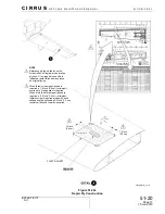
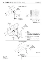
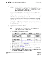
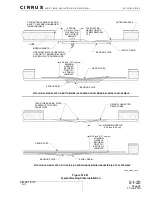
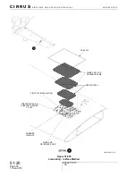
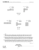
Backing plate installed to underside of repair area;
1
Define sanding area with marker and fill area with a cross-hatch of other random
pattern. Allow a short drying period before sanding until depth tracer is dry to the
touch.
2
Sand repair area in a random pattern until depth tracer is gone. Frequently clean
repair surface of contaminants using vacuum and paint brush.
3
Trimmed backing plate to final size. Verify size and shape of backing plate will not
interfere with other structure or systems.
Backing plate installed to topside of repair area;
4
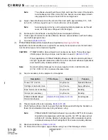
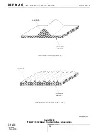
Sand backing plate and topside of laminate in a random pattern to form a scarf joint.
Frequently clean repair surface of contaminants using vacuum and paint brush.
Backing plate should be flush or slightly recessed to the surrounding laminate when
placed on topside of puncture.
5
Trim the backing plate to a maximum overlap of 0.25 inch (0.64 cm).
(c)
Place the backing plate into position.
(d)
If necessary, remove the peel ply from backing plate.
(e)
Solvent clean repair area.
Note:
If difficult to manipulate backing plate into place, attach a temporary handle
to plate with tape or hot glue.
(f)
If necessary, fasten backing plate to laminate with clecos or sheet metal screws during
bonding process.
(g)
Bond backing plate to laminate with 5 Minute Epoxy.

