background image

51-20

Page 4

All

EFFECTIVITY:

C I R R U S


A I R P L A N E   M A I N T E N A N C E   M A N U A L

M O D E L  S R 2 0

01 Jan 2012

2. MAINTENANCE PRACTICES

A. Machining Parameters

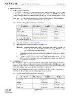
Some repairs or installations may require drilling a hole into the composite surface of the airplane. The 
following guidelines should be used when drilling into composite structure.

(1)

Drills 

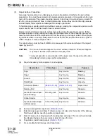
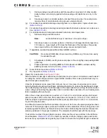
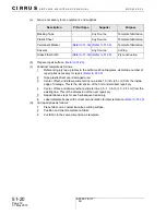
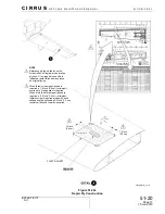
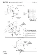
(See Figure 51-202)

(a)

Before drilling, verify path of drill bit is clear of any installed components, wire harnesses, 
or plumbing. When applicable, use a drill depth stop to avoid drilling deeper than neces-
sary.

(b)

When drilling over wires, wire harnesses or electronic equipment, cover area with plastic. 
Drill shavings can become lodged in wire bundles and wear through insulation, possibly 
causing electrical problems.

(c)

Drilling into a composite surface can cause delamination and a possible loss of structural 
integrity. To minimize delamination, drill at a high RPM with a very sharp or new drill bit.

(d)

Make sure that the hole is correctly aligned to the material surface. Control the drill by use 
of a suitable jig or bushed template.

(e)

Avoid forcing the drill bit into the material. Apply steady pressure and allow the drill to do 
the work. The inner circumference of the drilled hole may be sealed with 5 minute epoxy.

(f)

Prevent delamination and fiber damage on the exit face when drilling. Use back-up or 
break-out support material where possible.

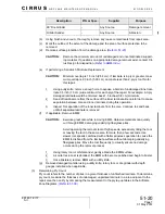
(2)

Drilling Technique
(a)

Before drilling, verify path of drill bit is clear of any installed components, wire harnesses, 
or plumbing. When applicable, use a drill depth stop to avoid drilling deeper than neces-
sary.

(b)

Drilling into a composite surface can cause delamination and a possible loss of structural 
integrity. To minimize delamination, drill at a high RPM with a very sharp or new drill bit.

(c)

Make sure that the hole is correctly aligned to the material surface. Control the drill by use 
of a suitable jig or bushed template.

(d)

Avoid forcing the drill bit into the material. Apply steady pressure and allow the drill to do 
the work. The inner circumference of the drilled hole may be sealed with 5 minute epoxy.

(e)

Prevent delamination and fiber damage on the exit face when drilling. Use back-up or 
break-out support material where possible.

(f)

Prevent delamination and fiber damage caused by overheating of the drill. Overheating of 
laminate is indicated by yellow or brown discoloration around perimeter of hole.

B. Metal Components - Corrosion Removal and Control

All corrosion products must be removed prior to refinishing. If they are not removed, corrosion will 
begin again, even though the affected area is refinished.

TBD

Summary of Contents for SR20 2010

Page 1: ...ning parameters are also discussed A General Information and Requirements Refer to Section 00 Standard Practices Structures for detailed information on personnel qualifica tions and safety information construction methods and Airframe Zone Diagrams Refer to 51 00 Section 10 Investigation contains guidance for identification of damage associated classifications and repairs and damage reporting proc...

Page 2: ...etely enclosed Temperature and humidity must be controlled so that the minimum temperature is 60 F 16 C with a corresponding relative humidity not greater than 71 percent and the maximum temperature is 75 F 24 C with a corresponding relative humidity not greater than 46 percent The area where surface cleaning of the laminates is done should be isolated from operations that generate dust oil vapors...

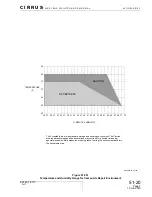
Page 3: ...1 33 35 37 39 41 43 45 47 49 51 53 55 57 59 61 63 65 67 69 71 73 55 60 65 70 75 80 85 ACCEPTABLE CAUTION TEMPERATURE F RELATIVE HUMIDITY The Acceptable area is the standard storage and bonding environment The Caution area indicates storage and bond operations may continue for a limited time under special procedures while measures are being taken to bring the environment back into the Acceptable ar...

Page 4: ...mference of the drilled hole may be sealed with 5 minute epoxy f Prevent delamination and fiber damage on the exit face when drilling Use back up or break out support material where possible 2 Drilling Technique a Before drilling verify path of drill bit is clear of any installed components wire harnesses or plumbing When applicable use a drill depth stop to avoid drilling deeper than neces sary b...

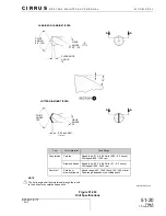
Page 5: ... be maintained through the insert to the drill point by carbide tipped drills NOTE CARBIDE OR CARBIDE TIPPED CUTTER DIAMOND TIPPED 0 04 inch MIN 1 mm Tool Cutter Material Feed Range Countersink Carbide Speed feed 0 16 0 66 ft min 0 05 0 2 m min Drill speed 800 1200 rpm Diamond tipped Speed feed 0 33 0 98 ft min 0 1 0 3 m min Drill speed 1200 2400 rpm Carbide or diamond tipped Speed range 492 1640 ...

Page 6: ...imer is exposed 2 For primer and paint removal sand surface until the laminate is exposed For hand sanding use 120 240 grade emery cloth If sanding with orbital sander use 80 120 grade aluminum oxide paper 2 Damage Removal The strength of a composite repair relies upon the integrity of the undamaged and uncontami nated supporting material It is importance that repair surface preparation is carried...

Page 7: ...ore Continue to sand back until all separated laminate is removed f If applicable Remove EMM CAUTION Exercise great care while removing EMM Abrasive materials can quickly cut through EMM damaging underlying fiberglass plies Avoid operating the removal tool at high speeds excessively tilting the tool or leaving the tool in the same area for more than a few seconds Use slower tool speeds combined wi...

Page 8: ... to verify the number of plies Refer to 51 00 4 Determining Ply Orientation See Figure 51 203 The glass fabric used for repair on this airplane is Hexcel 7781 This fabric is considered a bal anced cloth because approximately 50 of the fibers run parallel to warp and approximately 50 run perpendicular to warp Fibers that run parallel to the selvage edge have a fiber orienta tion of 0 The warp clock...

Page 9: ...C E M A N U A L M O D E L S R 2 0 51 20 Page 9 All EFFECTIVITY Figure 51 203 Determining Ply Orientation 45 0 45 90 SPECIAL BALANCED FIBERGLASS TYPE 7781 FABRIC BOLT SR20_MM51_1190A SELVAGE EDGE FILL WARP 0 AXIS WARP CLOCK TOOL SURFACE 15 Jun 2010 ...

Page 10: ...Replace or clean sandpaper often The repair surface must be free of EMM in an area equal to the size and shape of the largest repair ply plus 0 5 CAUTION Do not use chemical strippers to remove surface protection Chemical strippers may leave a residue and breakdown the epoxy resin Note To prevent possible re contamination of the repair area the repair must be done immediately following repair surf...

Page 11: ...1 20 6 Repair Ply Construction See Figure 51 204 After the extent of damage is determined repair plies may be made A template is used to assist in cutting the correct shape and size of glass fabric Release film or clear plastic sheet may be used for template construction Once the template is made glass fiber cloth can be cut Use clean sharp scissors or a razor knife Dull tools will catch and pull ...

Page 12: ...est repair ply 4 Center offset and draw another perimeter line 0 5 1 0 inch 1 3 2 5 cm from the existing line This is the dimension of the next repair ply 5 Repeat above steps for each subsequent repair ply 6 Label template boxes with correct ply orientation for later reference Refer to 51 20 d Cut repair plies as follows 1 Place fabric on a contaminate free cutting surface 2 Position and orient t...

Page 13: ... 4 0 375 9 525 2 14 6 31 5 15 7 32 5 16 4 0 375 9 525 3 33 2 0 375 9 525 2 17 9 34 3 0 to 1 0 2 5 to 1 0 3 5 to 1 0 2 0 to 1 0 2 0 to 1 0 2 0 to 1 0 3 0 to 1 0 2 0 to 1 0 3 0 to 1 0 2 0 to 1 0 2 5 to 1 0 3 5 to 1 0 3 5 to 1 0 3 0 to 1 0 2 0 to 1 0 2 5 to 1 0 2 5 to 1 0 3 5 to 1 0 4 0 to 1 0 2 5 to 1 0 2 5 to 1 0 2 0 to 1 0 1 5 to 1 0 2 0 to 1 0 1 5 to 1 0 1 5 to 1 0 2 0 to 1 0 2 0 to 1 0 2 5 to 1 ...

Page 14: ...ith release film Remove all wrinkles e Offset and draw perimeter line on release film 1 0 inch 2 5 cm from the inside edge of hole This is the dimension of the backing plate f Cut backing plate plies to the same dimension as perimeter line g Mix non structural resin Refer to 51 30 h Construct backing plate using Laminating by Transfer method Refer to 51 20 8 Water Break Test CAUTION The following ...

Page 15: ...re can cause composite structure dis bonding or delamination both inside and outside the repair area due to due steam pressure gen erated during the cure cycle Since there is no practical method for quantifying the moisture content of a composite structure the structure should always be considered as saturated Even when the composite structure is visually dry it is necessary to perform a final dry...

Page 16: ...ructure ensuring temperature is raised at a rate not greater than 1 0 5 0 F 0 6 2 8 C per minute 7 Monitor temperature and dry structure for two hours 8 Remove heat from structure ensuring temperature is lowered at a rate not greater than 1 0 15 0 F 0 6 8 4 C per minute 9 Let structure cool to room temperature before beginning repair d Drying Using Hot Air See Figure 51 205 To supply heated air us...

Page 17: ...ucture Do not exceed part temperature of 195 F 91 C 7 Apply required heat to structure ensuring temperature is raised at a rate not greater than 1 0 5 0 F 0 6 2 8 C per minute 8 Periodically monitor temperature using infrared thermometer and dry structure for two hours 9 Remove heat from structure ensuring temperature is lowered at a rate not greater than 1 0 15 0 F 0 6 8 4 C per minute 10 Let str...

Page 18: ... TEMPERATURE F C 10 inches 254 mm H H X PROBE PROBE 1500W 1875W HOT AIR DRYER 250W HEAT LAMP 250W HEAT LAMP GRAPH 1 HOT AIR DRYER METHOD METHOD 1 Construct Graph 1 to show the temperature at the center of the heated area as a function of the distance between the heat lamp and surface NOTE METHOD 2 Use electronic temperature control to maintain constant heat RADIANT HEAT METHODS Periodically check ...

Page 19: ... the surface with clean water and an abrasive pad Dry the surface with plain white paper towels to remove the dissolved blush before it dries on the surface After washing with the abrasive pad the surface should appear dull Sand any remaining glossy areas 2 MGS L418 Based Structural Adhesive Application Application of structural adhesive is required for secondary bond repairs where the technician ...

Page 20: ... taken to avoid it Refer to 51 20 Proper application of PTM W ES6292 adhesive is critical to obtaining full bond strength Application procedures differ from other structural adhesive applications and should be fully understood before mixing Note Nominal bondline thickness for structural repair is 0 060 0 020 0 055 inch 0 152 0 051 0 140 cm unless otherwise noted a Acquire necessary tools equipment...

Page 21: ... in thin layer between peaks f On the second surface apply a bead of adhesive Adhesive bead should have a high point near center of bead to avoid entrapped air When more than one bead is required apply immediately adjacent to prior bead to form one large bead Note Avoid applying removing and re applying clamping pressure as this will cause air to become entrapped in the bond gap g Secure parts in ...

Page 22: ... A I N T E N A N C E M A N U A L M O D E L S R 2 0 15 Jun 2010 Figure 51 206 PTM W ES6292 Based Structural Adhesive Application APPLICATION OF ADHESIVE BEAD APPLICATION OF V NOTCH TROWEL LAYER ADHESIVE COMPOSITE SURFACE ADHESIVE COMPOSITE SURFACE SR20_MM51_2997 ...

Page 23: ...pair area must be manufactured on a surface with a similar shape to the damaged area The backing plate shall be approximately 1 0 inch 2 5 cm larger than the diameter of the hole it is bridging If the underside of puncture is not accessible the backing plate must be installed on the topside of the puncture This is accomplished by sanding the repair area and backing plate to a matched taper to form...

Page 24: ...systems Backing plate installed to topside of repair area 4 Sand backing plate and topside of laminate in a random pattern to form a scarf joint Frequently clean repair surface of contaminants using vacuum and paint brush Backing plate should be flush or slightly recessed to the surrounding laminate when placed on topside of puncture 5 Trim the backing plate to a maximum overlap of 0 25 inch 0 64 ...

Page 25: ...NER LAMINATE OUTER LAMINATE INNER LAMINATE BACKING PLATE USE SHEET METAL SCREWS OR CLECOS TO TEMPORARILY HOLD BACKING PLATE DURING CURE EPOXY RESIN TAPER AFTER RESIN CURES SCREW REMOVAL 1 50 ATTACH BACKING PLATE ON BOTTOM SIDE AS SHOWN ABOVE WHEN BACKSIDE IS ACCESSIBLE TAPER THE BACKING PLATE LAMINATE TO FORM A SCARF JOINT ATTACH BACKING PLATE ON TOP SIDE AS SHOWN ABOVE WHEN BACKSIDE IS NOT ACCESS...

Page 26: ...ss c Sand off residual core from the surface of the inner laminate Be careful not to cause sep aration between core and inner laminate during this operation d Inspect for separation of the inner laminate from the core Continue to sand back until all separated laminate is removed e Fabricate core replacement to fit repair area with a maximum gap of 0 10 inch 0 25 cm and thickness to match core area...

Page 27: ...lacement part and exist ing repair area in a random pattern so that scarf joint tapers to a 1 50 ratio i e taper length is 50 times the thickness of the laminate Frequently clean repair surfaces of con taminants using vacuum and paint brush e Verify replacement part fit up to existing repair area has a maximum gap of 0 10 inch 2 54 mm f Prepare bond surface by sanding inner laminate with 80 to 120...

Page 28: ...plicable prepare EMM surfaces Refer to 51 20 f If necessary mix MGS L418 based filler paste and apply to fill any dents gouges or other voids in prepared repair surface Refer to 51 20 g Mix structural resin Refer to 51 30 h If applicable remove clecos or sheet metal screws used to temporarily attach backing plate to laminate i Lay up glass fabric as follows 1 Apply thin coat of resin to repair are...

Page 29: ...h 2 Apply peel ply over repair area 3 Lightly flatten the ply with the brush Allow time for resin to wick through the ply from below Note Peel ply can be worked more aggressively than repair plies and becomes transparent when saturated with resin 4 Stipple or tap the ply to work air bubbles to the edge of the ply If necessary add resin to saturate dry areas k Cure repair Refer to 51 20 l If applic...

Page 30: ...A N C E M A N U A L M O D E L S R 2 0 15 Jun 2010 Figure 51 208 Laminating In Place Method SR20_MM51_2120 WARP AXIS OR 0 REFERENCE LINE DAMAGED LAMINATE 45 0 45 90 PEEL PLY REPAIR PLIES WARP AXIS REFERENCE LINE PREPARED FAYING SURFACE TAPERED TO 1 50 FIRST PLY INSTALLATION ...

Page 31: ...ermost ply only Ensure peel plies are removed prior to secondary bonding Do not bond plies on top of peel ply a Acquire necessary tools equipment and supplies b If applicable prepare backing plate Refer to 51 20 c Prepare repair area Refer to 51 20 d Prepare repair plies Refer to 51 20 e If applicable prepare EMM surfaces Refer to 51 20 f Cut two sheets of release film approximately 6 inches 15 cm...

Page 32: ...g a clean brush o Peel second sheet of release film away from the last repair ply laid up on the stack p Carefully lift stacked repair plies and turn over so smallest repair ply is on bottom q Using the warp axis and or 0 reference line align center and install stacked plies to repair area r Peel remaining sheet of release film away from stacked plies s Stipple or tap the ply to work air bubbles t...

Page 33: ...ITY Figure 51 209 Laminating Transfer Method SR20_MM51_2122 REPAIR PLIES PEEL PLY 45 0 45 90 RELEASE FILM PEEL PLY 90 45 0 45 PREPARED FAYING SURFACE TAPERED TO 1 50 WARP AXIS REFERENCE LINE DAMAGED LAMINATE WARP AXIS OR 0 REFERENCE LINE Remove release film before installation NOTE RELEASE FILM 15 Jun 2010 ...

Page 34: ...e EMM is installed a Acquire necessary tools equipment and supplies CAUTION Do not lay repair plies over EMM Replacement EMM must be installed over top layer of repair b Using 80 grade sand paper or finer burnish existing EMM until shiny Frequently clean surface of contaminants using vacuum and paint brush to ensure EMM is not damaged c Using 80 grade sand paper or finer burnish replacement EMM un...

Page 35: ...ller paste to cure one hour m Mix non structural Epon 862 or L285 H287 resin Refer to 51 30 n Apply a coat of resin to repair area with a clean brush o Apply peel ply over EMM repair surface p Apply both pieces of glass repair fabric over EMM This temporarily installed fabric adds weight and rigidity to the repair which helps ensure the EMM fully contacts the underlying repair surface q Apply a co...

Page 36: ...ts that do not overlap but require that the EMM pieces are as close as possible to each other Gaps between materials on butt joints can be up to but not exceed 0 187 inch 0 475 cm When sections of EMM run parallel for lengths greater than 2 0 feet 0 6 m the butt joint gap may exceed 0 187 inch 0 475 cm for up to 12 0 inches 30 5 cm and not more than 25 of the overall butt joint length Butt joint g...

Page 37: ...t edges When thermal blankets are used multiple thermocouples are required This is because thermocouple failures are common and replacement during a running cure is virtually impossible Also temperatures can easily vary widely across a repair area during cure 60 80ºF 35 45ºC spreads are not uncom mon Other curing techniques such as vacuum bagging and ovens may also be used if available and the tec...

Page 38: ...our at 120 210 F 49 99 C Post 5 hours at 180 210 F 82 99 C Structural High Temperature Paste Adhesive Hysol EA 9395 Basedb 9395 A 9395 B Initial 30 mins at 125 210 F 52 99 C or 24 hours at 65 210 F 18 99 C Post 1 hours at 200 210 F 93 99 C Non Structural Resin Repair System Epon Based Epon 862 Epicure 3234 Initial 24 hours at 65 75 F 18 24 C or 3 hours at 120 210 F 49 99 C or 1 hours at 150 210 F ...

Page 39: ... 75 F 18 24 C or 3 hours at 120 210 F 49 99 C or 1 hours at 150 210 F 66 99 C Post 2 hours at 150 210 F 66 99 C a Serials 1815 and subsequent with high temperature firewall only Engine compartment side only b Serials 1815 and subsequent with high temperature firewall only Engine compartment side only Type P N or Spec Cure Cycle Figure 51 2011 Cure Temperatures and Times Continued 15 Jun 2010 ...

Page 40: ...lean area where bag will be attached Refer to 20 30 c Attach thermocouple monitor and electronic temperature control unit probes near repair area d Construct enclosure around repair area using bagging film material and masking tape e Place a small slit in bagging film material and use masking tape to attach blow dryer with breather insulation wrapped around the outlet to prevent scuffing f Place m...

Page 41: ... q Connect thermocouple probes to the electronic temperature control unit r Turn electronic temperature control unit ON Set electronic temperature control unit to desired shut off temperature s Turn blow dryer on and if necessary cover enclosure with insulation to achieve specific cure temperature readings on thermocouple reader See Figure 51 2012 t When cure temperature is stabilized press the PR...

Page 42: ...od SR20_MM51_1693A 2 4 Keep flashbreaker tape off airplane finish Place breather material under outlet to prevent scuffing NOTE 1 3 1 6 2 1 LEGEND 1 Flashbreaker Tape 2 Bagging Film Breather 3 Masking Tape 4 Blow Dryer 5 Bagging Film 6 Thermocouple Probe 7 Temperature Sensor 8 Thermocouple Monitor Recorder 9 Electronic Temperature Control 2 5 6 3 3 7 9 8 ...

Page 43: ...On fuselage aft of baggage compartment bulkhead in addition to registration markings total stripe width shall not exceed 51 of fuselage height per side If stripe width is mea sured along the contour then fuselage height should also be measured along the contour from top center to bottom center If stripe width is measured by horizontal projection then fuselage height should also be measured by hori...

Page 44: ...er thickness shall not exceed 0 13 inch 3 3 mm No more than 15 of the surface may be covered with body filler and no more than 5 of the surface area shall have filler thicker than 0 10 inch 2 5 mm Body filler thickness in small local areas less the 10 square inches or at seams and joints may exceed maximum filler thickness Filler thickness can be measured by inserting the pointed end of a toothpic...

Page 45: ...raight primer when surfacer is being used Usually surfacer will be applied in three individual coats Primer is used to help paint adhere to the airplane a Acquire necessary tools equipment and supplies b Mask off all surfaces that do not require primer or where primer is not permitted c Lightly sand the application area for primer with at least 320 grade sandpaper d Blow surface clean with compres...

Page 46: ...ade wet dry sandpaper and solvent cleaned prior to painting As an alternative to wet sanding the entire surface may be abraded with a fine grade of Scotchbrite Scotchbrite will not flatten the surface only remove gloss Wet sand if the surface requires flattening Single Stage top coat thickness shall be applied in accordance with the manufacturer s data sheet Maximum top coat thickness may be excee...

Page 47: ... primer with 320 grade sand paper h Visually inspect prepared surface for imperfections prior to application of paint Rework and solvent clean any damaged or defective areas Refer to 20 30 i Solvent clean application area Refer to 20 30 j Wipe entire area to be painted with a tack cloth CAUTION If using base clear coat paint system the base coat must be mixed as cata lyzed system k Mix and apply p...

Page 48: ...51 20 Page 48 All EFFECTIVITY C I R R U S A I R P L A N E M A I N T E N A N C E M A N U A L M O D E L S R 2 0 15 Jun 2010 Intentionally Left Blank ...

Reviews: