


Reviews:
No comments
Related manuals for Nanogun Airmix H2O

1342
Brand: Laser Pages: 2

12855
Brand: FarmTek Pages: 7

08-823
Brand: NEO TOOLS Pages: 12

352083 2007
Brand: Parkside Pages: 78

506300
Brand: ujk technology Pages: 28

102946
Brand: ujk technology Pages: 12

643115
Brand: Silverline Pages: 2

585 E1
Brand: Alemite Pages: 66

999320
Brand: Northern Pages: 11

BOILER GUN OD
Brand: H&S Pages: 2

PAT 4 B2
Brand: Parkside Pages: 109

KHP-20T-GGN
Brand: King Canada Pages: 6

GATOR EK06ATCL
Brand: Greenlee Pages: 12

Muyang SZLH Series
Brand: Famsun Pages: 46

MX-7-420 TURBO-PROP
Brand: MAULE Pages: 40

BTS-1
Brand: Park Tool Pages: 4
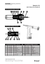
Textron Genesis G1
Brand: Avdel Pages: 2

CoreMax SCFTP0620
Brand: FasTest Pages: 2


