


CG Drives & Automation, 01-5326-01r5
Main Features
61
7.
Main Features
This chapter contains descriptions of the main features of
the AC drive.
7.1
Parameter sets
Only valid if the option HCP - Handheld Control Panel is
used.
Parameter sets are used if an application requires different
settings for different modes. For example, a machine can be
used for producing different products and thus requires two
or more maximum speeds and acceleration/deceleration
times. With the four parameter sets different control options
can be configured with respect to quickly changing the
behaviour of the AC drive. It is possible to adapt the AC
drive online to altered machine behaviour. This is based on
the fact that at any desired moment any one of the four
parameter sets can be activated during Run or Stop, via the
digital inputs or the control panel and menu [241].
Each parameter set can be selected externally via a digital
input. Parameter sets can be changed during operation and
stored in the control panel.
Define parameter sets
When using parameter sets you first decide how to select
different parameter sets. The parameter sets can be selected
via the control panel, via digital inputs or via serial
communication. All digital inputs and virtual inputs can be
configured to select parameter set. The function of the
digital inputs is defined in the menu [520].
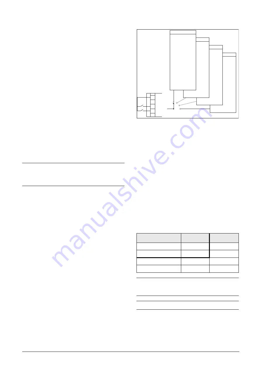
Fig. 69 shows the way the parameter sets are activated via
any digital input configured to Set Ctrl 1 or Set Ctrl 2.
Fig. 69 Selecting the parameter sets
Select and copy parameter set
The parameter set selection is done in menu [241], “Select
Set”. First select the main set in menu [241], normally A.
Adjust all settings for the application. Usually most
parameters are common and therefore it saves a lot of work
by copying set A>B in menu [242]. When parameter set A is
copied to set B you only change the parameters in the set
that need to be changed. Repeat for C and D if used.
With menu [242], Copy Set, it is easy to copy the complete
contents of a single parameter set to another parameter set.
If, for example, the parameter sets are selected via digital
inputs, DigIn 3 is set to Set Ctrl 1 in menu [523] and DigIn
4 is set to Set Ctrl 2 in menu [524], they are activated as in
Table 25.
Activate the parameter changes via digital input by setting
menu [241], “Select Set” to DigIn.
NOTE: The only data not included in the parameter
set is Motor data 1-4, (entered separately), language,
communication settings, selected set, local remote,
and keyboard locked.
Table 25
Parameter set
Parameter set
Set Ctrl 1
Set Ctrl 2
A
0
0
B
1
0
C
0
1
D
1
1
NOTE: The selection via the digital inputs is
immediately activated. The new parameter settings
will be activated on-line, also during Run.
NOTE: The default parameter set is parameter set A.
{
(NG06-F03_1)
Run/Stop
-
-
Torques
-
-
Controllers
-
-
Limits/Prot.
-
-Max Alarm
Parameter Set A
Set B
Set C
Set D
11
10
16
Set Ctrl1
Set Ctrl2
+24 V
Summary of Contents for Emotron VFX Series
Page 1: ...Emotron VFX 2 0 AC drive Instruction manual English Valid from software version 4 42...
Page 2: ......
Page 4: ......
Page 10: ...6 CG Drives Automation 01 5326 01r5...
Page 50: ...46 Installation CG Drives Automation 01 5326 01r5...
Page 62: ...58 Getting Started CG Drives Automation 01 5326 03r5...
Page 74: ...70 EMC and standards CG Drives Automation 01 5326 01r5...
Page 90: ...86 Operation via the Control Panel CG Drives Automation 01 5326 01r5...
Page 218: ...216 CG Drives Automation 01 5326 01r5...
Page 226: ...224 Troubleshooting Diagnoses and Maintenance CG Drives Automation 01 5326 01r5...
Page 236: ...234 Options CG Drives Automation 01 5326 01r5...
Page 256: ...254 Technical Data CG Drives Automation 01 5326 01r5...
Page 267: ......


