Cattron™ MP96/48 Series Portable Remote Control Systems
User Manual
93
68C-MP96/48-RD-EN
Version 006
7.10.7 EPROM Replacement
CAUTION
EPROMS ARE ELECTROSTATIC SENSITIVE DEVICES. USE AN ANTI-STATIC MAT AND
PERSONAL GROUNDING STRAP (WRIST) WHEN REPLACING OR INSTALLING EPROMS.
FAILURE TO COMPLY WITH THIS CAUTION MAY RESULT IN EQUIPMENT DAMAGE AND WILL
VOID OUR WARRANTY.
Replace an EPROM as follows:
1. Open the cover of the receiver/decoder.
2. Remove power from the e
lectronics chassis, or ‘Gold Box’, by turning off the circuit breaker on the
bottom.
3. Release the four captive screws and remove the lid from the Gold Box.
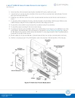
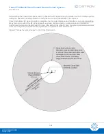
4. Find the EPROM located on the decoder circuit board. The EPROM locations are shown in Figure 23.
5. Observe and record the exact orientation of the EPROM within its circuit board location.
6. Remove the EPROM.
7. Carefully install the new EPROM in the vacated circuit board location, making sure its orientation is
exactly the same as recorded in step 5 above.
8. Install the lid on the Gold Box and secure using the four captive screws.
9. Restore power to the receiver/decoder by turning on the circuit breaker on the bottom of the Gold Box.
10. Close the cover of the receiver/decoder.
11. Perform a functional check of the PRC System (refer to the System Checkout section of this manual).
12. Return the EPROM to Cattron.
7.10.8 Power Supply Module Replacement
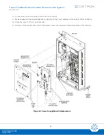
Referring to Figure 25, replace the power supply module as follows:
1. Open the cover of the receiver/decoder enclosure.
2. Remove power from the e
lectronics chassis, or ‘Gold Box’, by turning off the circuit breaker on the
bottom.
3. Disconnect the power input plug from the main power supply.
4. Release the four captive screws and remove the lid from the Gold Box.
5. Disconnect the VAC input connectors, the external DC input connector and the DC output connector from
their respective terminals and headers on the power supply module.
6. Remove the four mounting screws and withdraw the power supply module from the Gold Box pillars.
7. Install the new power supply module to the Gold Box pillars and secure with the four mounting screws.
8. Connect the DC output connector, the external DC input connector and the VAC input connectors to their
respective headers and terminals on the power supply module.
9. Install the lid on the Gold Box and secure by tightening the four captive screws.
!


